Method and apparatus for supplying energy to an implant

a technology for energy supply and implants, applied in the direction of prosthesis, artificial respiration, therapy, etc., can solve the problems of disturbing the intended medical effect of the device, affecting the efficiency of energy transfer, and the energy supplied to the medical device may also increase dramatically, so as to achieve faster charging, increase the life-time of the charging occasion, and increase the energy charging rate

Active Publication Date: 2011-08-11
FORSELL PETER
View PDF24 Cites 64 Cited by
  • Summary
  • Abstract
  • Description
  • Claims
  • Application Information

AI Technical Summary

Benefits of technology

[0111]When using the first and second storage devices in the energy storage device, the first storage device may be adapted to be charged at a relatively higher energy charging rate as compared to the second storage device, thereby enabling a relatively faster charging. The first storage device may also be adapted to be charged at multi

Problems solved by technology

Furthermore, the position of the external energy source relative to the implanted internal energy receiver is a factor that affects the efficiency of the energy transfer, which highly depends on the distance and relative angle between the source and the receiver.
If the transfer efficiency becomes low, the amount of energy supplied to the medical device may be insufficient for operating the device properly, so that its action must be momentarily stopped, naturally disturbing the intended medical effect of the device.
On the other hand, the energy supplied to the medical device may also increase drastically, if the relative positions of the external source and the internal receiver change in a way that unintentionally increases the transfer efficiency.
This situation can cause severe problems since the implant cannot “consume” the suddenly very high amoun

Method used


Image

  • Method and apparatus for supplying energy to an implant
  • Method and apparatus for supplying energy to an implant
  • Method and apparatus for supplying energy to an implant

Examples


Embodiment Construction

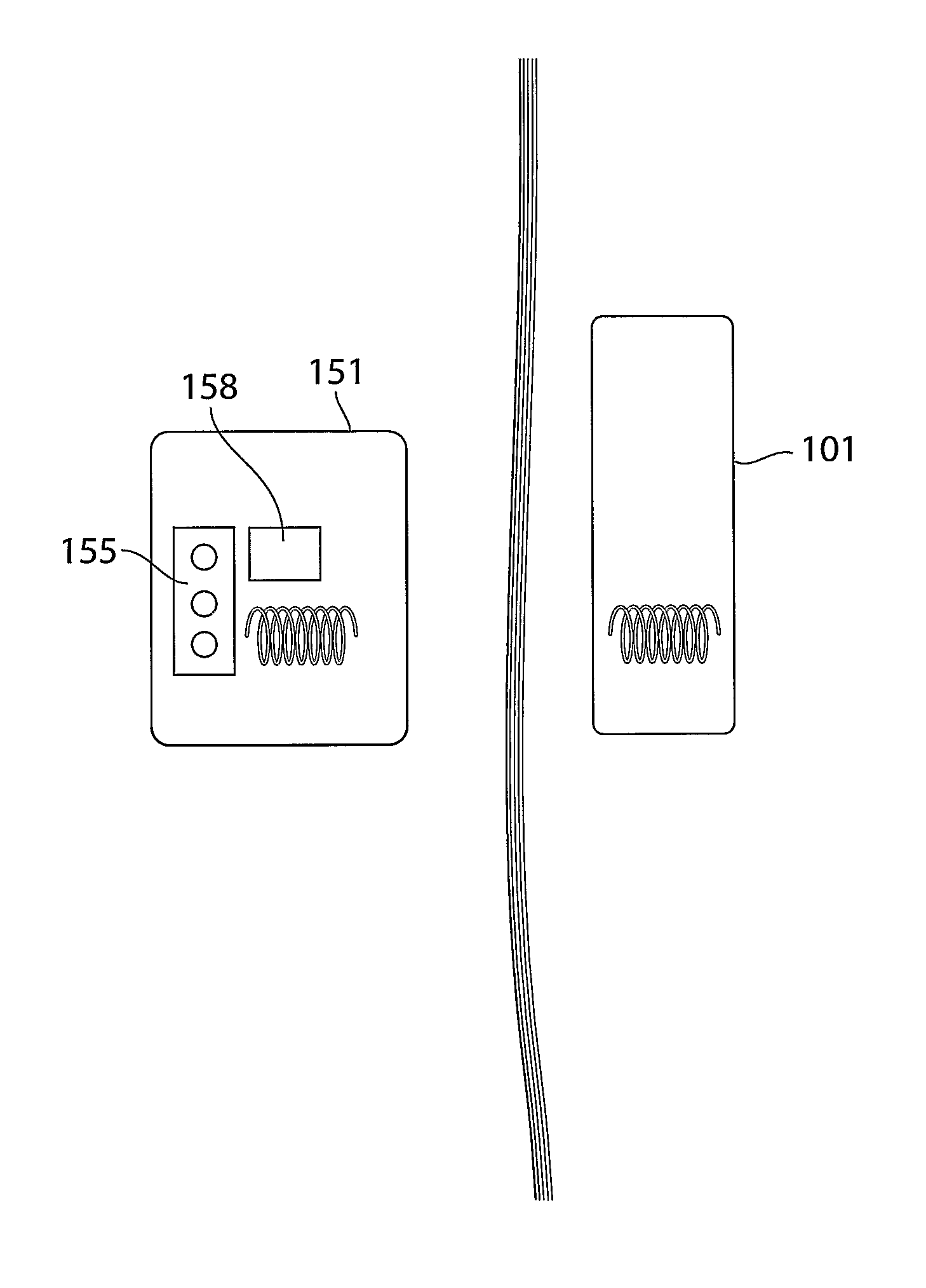
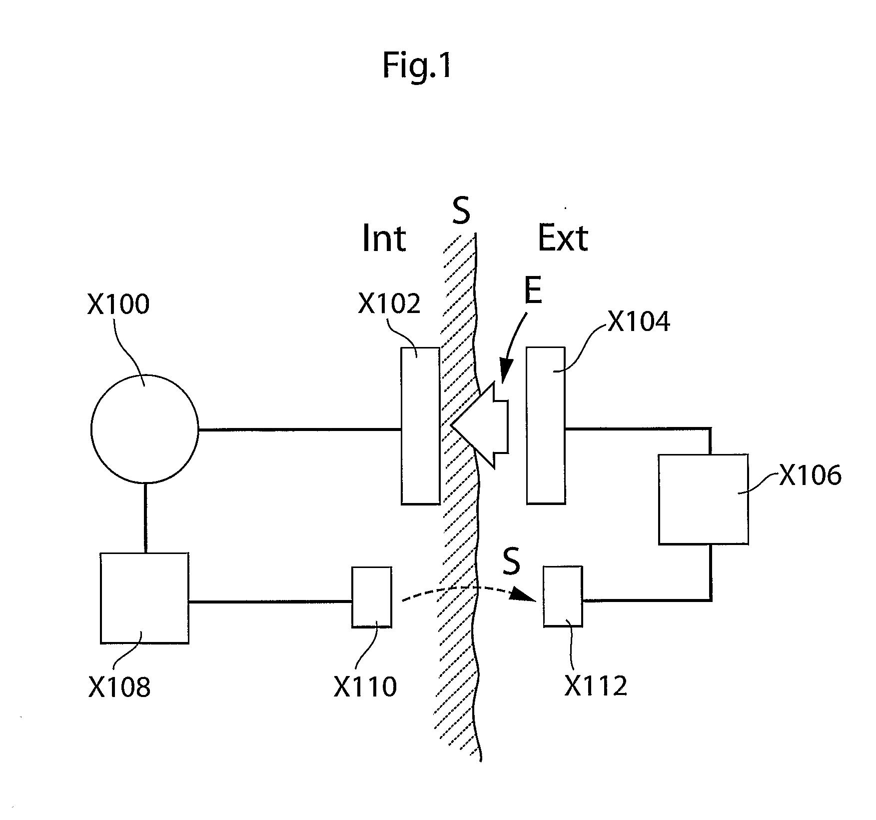
[0181]FIG. 1 shows a first embodiment of a system of the invention. As shown in FIG. 1, the system comprises an implantable medical device X100 which is electrically powered and which is shown in FIG. 1 as being implanted in a patient, the skin of the patient being indicted in FIG. 1 by means of a line S. As shown in FIG. 1, the medical device also comprises an internal energy receiver X102 which is arranged to power the medical device.

[0182]The system also comprises an external energy source X104 which, as shown in FIG. 1, is adapted to be located externally to the patient for wireless supplying energy to the internal energy receiver X102.

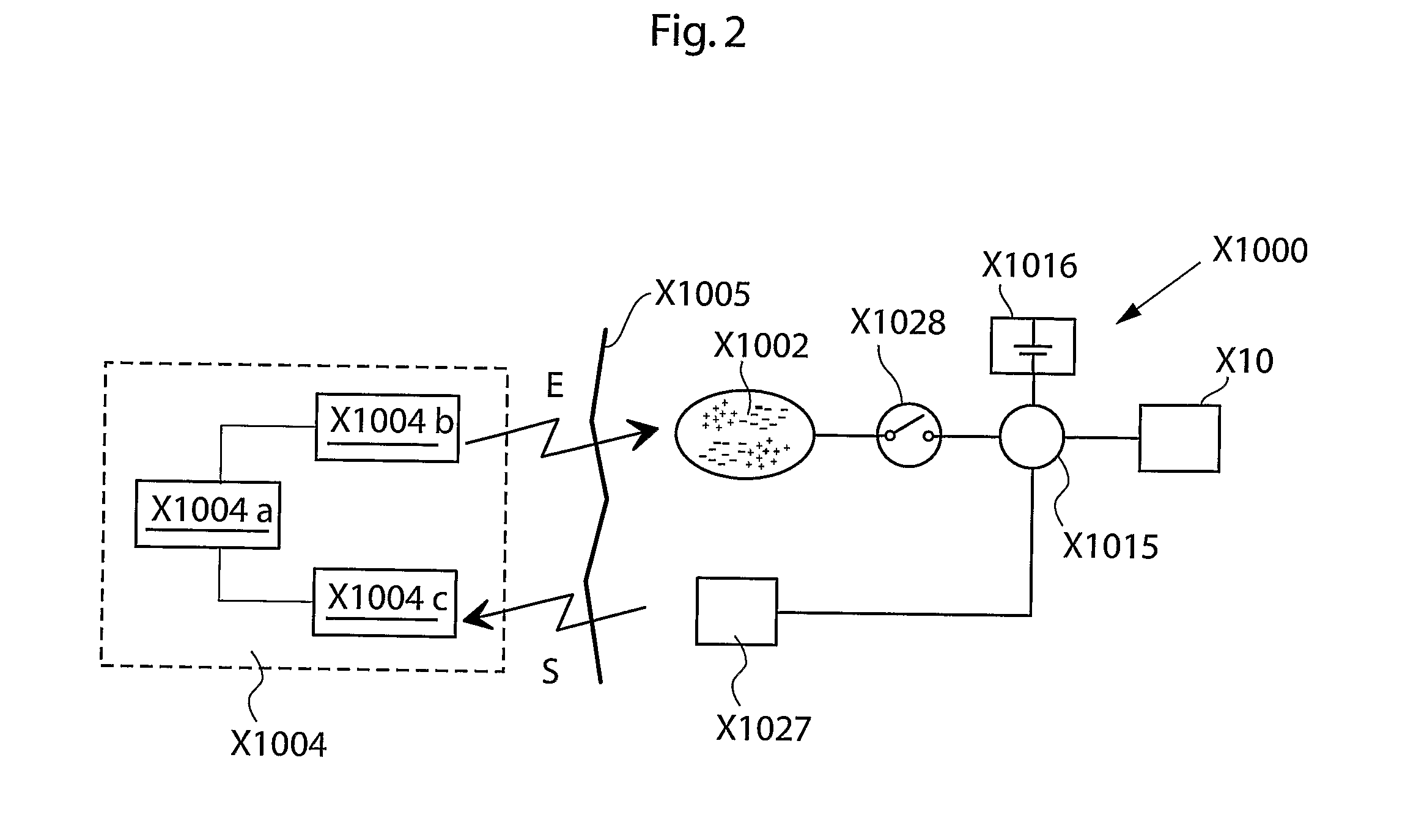
[0183]Versions of one embodiment of the invention will now be described by means of reference to FIG. 1 and FIGS. 4-8.

[0184]As shown in FIG. 4, the external energy source X104 is equipped with a primary coil X11, L1, from which the external energy source X104 is arranged to transmit energy inductively to a first secondary coil X10, L2, in the inte...


PUM


Abstract

A system is disclosed which comprises an implantable electrical medical device (100) with an internal energy receiver (102). The system also comprises an external energy source (104) located externally for supplying wireless energy to the internal energy receiver (102). The external energy source (104) has a primary coil (11) for transmitting energy inductively to a first secondary coil (10) in the energy receiver (102). The system is arranged to measure parameters related to a first coupling factor (C1) between the primary and the first secondary coil (10), and the external energy source (104) is adapted to transmit energy to the energy receiver (102) for enabling the medical device (100) to detect information related to the first coupling factor (C1). The medical device (100) is adapted to wirelessly send feedback information related to said first coupling factor (C1) to the external energy source (104) with the external energy source (104) being arranged to receive the feedback information and to perform a predetermined action based on said feedback information.

Description

TECHNICAL FIELD[0001]The present invention relates generally to a method and apparatus for using a coupling factor between a device which is implantable in a patient and device which is external to the patient in order to perform an action.BACKGROUND[0002]Medical devices, designed to be implanted in a patient's body, are typically operated by means of electrical power. Such implantable medical devices include electrical and mechanical stimulators, motors, pumps, etc, which are designed to support or stimulate various body functions. Electrical power can be supplied to such an implanted medical device from a likewise implanted battery or from an external energy source that can supply any needed amount of electrical power intermittently or continuously without requiring repeated surgical operations.[0003]An external energy source can transfer wireless energy to an implanted internal energy receiver located inside the patient and connected to the medical device for supplying received e...

Claims


Application Information

Patent Timeline
IPC IPC(8): A61N1/36
CPCA61F2250/0001H02J7/025A61N1/3787A61N1/37223H02J50/90H02J50/80H02J50/10
Inventor FORSELL, PETER
Owner FORSELL PETER
Why Eureka
Try Eureka