Angled Rolled Plan Rack

a technology of rolled plan and angled shelves, which is applied in the direction of storage devices, fittings, and display hangers, etc., can solve the problems of not being able to adapt to a panel mount configuration, not being able to adapt to a varying width of plans, and not having any means, so as to achieve the effect of being easily seen and identified

Inactive Publication Date: 2011-08-18
GEOFFREY PAMELA A
View PDF82 Cites 3 Cited by
  • Summary
  • Abstract
  • Description
  • Claims
  • Application Information

AI Technical Summary

Benefits of technology

[0008]It is one of the main objects of the present invention to provide a rolled plan rack that has the capacity to hold many rolled plans or other large format print media on each of a multiplicity of angled shelves. An added advantage is that each individual plan's title block may be easily seen and identified.
[0009]It is another object of this invention to provide a rolled plan rack that while supporting many rolled plans each individual plan may be easily accessed from the rack without removing or disturbing the plans remaining on the rack.
[0010]It is still another object of the present invention to provide a rack for rolled plans or other large format rolled print media that allows easy organization of many plans on a single rack and permits the replacement of plans in an orientation that displays the title block of the plans for simple identification of any plan on the rack.
[0012]It is another object of the present invention to provide enhanced storage capacity of plans and / or other printed media using minimal floor space.
[0013]It is yet another object of this invention to provide such a device that is inexpensive to manufacture and maintain while retaining its effective function.

Problems solved by technology

None of them, however, includes an angled rack that holds numerous large format rolled plans oriented in a manner that allows easy viewing of the label to identify the plans while retaining the ability to easily remove any selected plan without removing other plans held in the rack or other undue difficulty.
However, it differs from the present invention because the Bailey device is limited to fixed width applications, does not allow for multiple plans to be supported by each shelf, does not have any means to prevent plans from falling off the front of the shelf, is not adaptable to a panel mount configuration and is not adaptable for varying width of plans.
However, it differs from the present invention because the Lusk device is limited to fixed width applications, only allows for a single layer of plans to be supported by each shelf, does not have sufficient means to prevent plans from falling off the front of the shelf, is not adaptable to a panel mount configuration and is floor mounted which unnecessarily uses too much space.

Method used


Image

  • Angled Rolled Plan Rack
  • Angled Rolled Plan Rack
  • Angled Rolled Plan Rack

Examples


Embodiment Construction

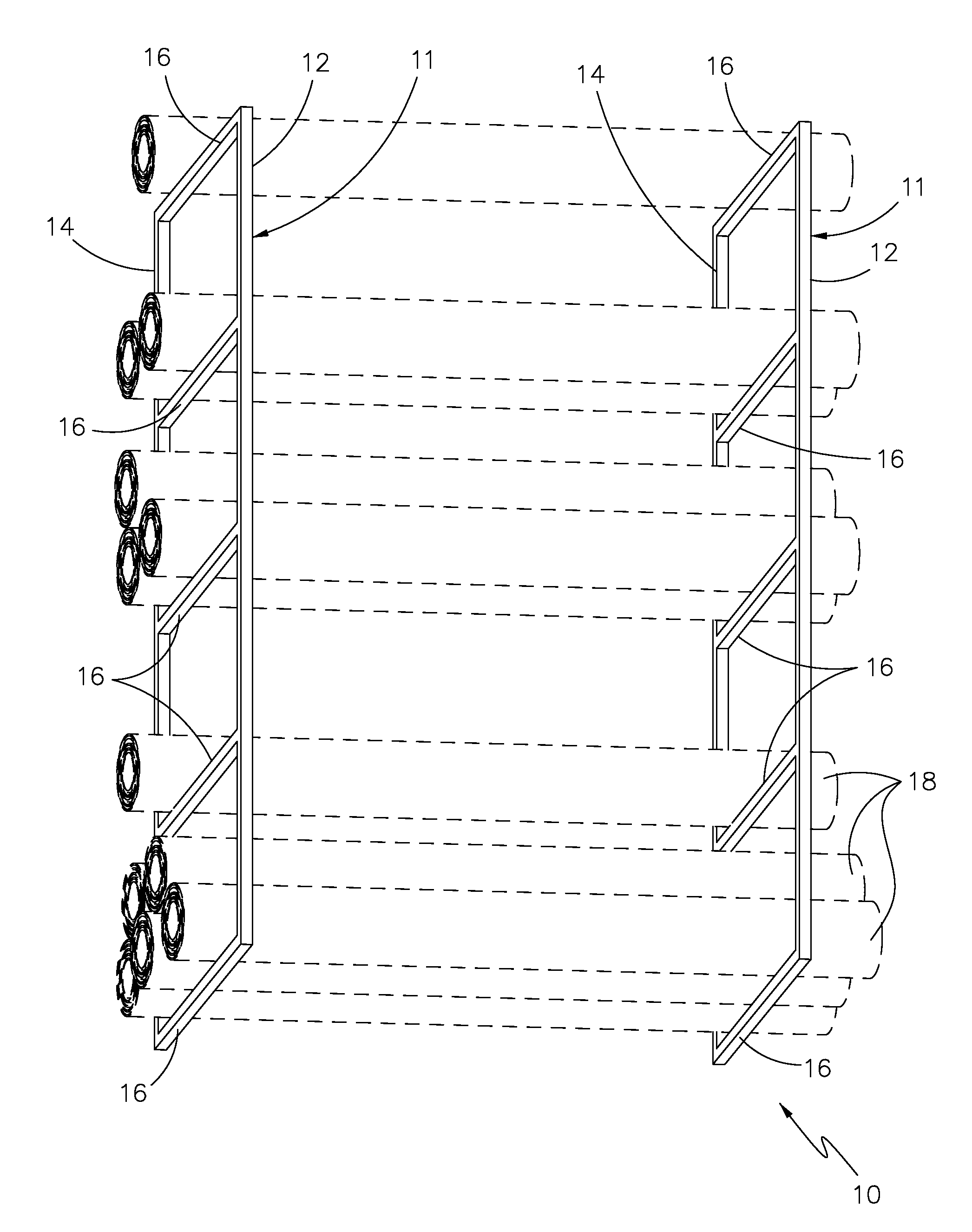
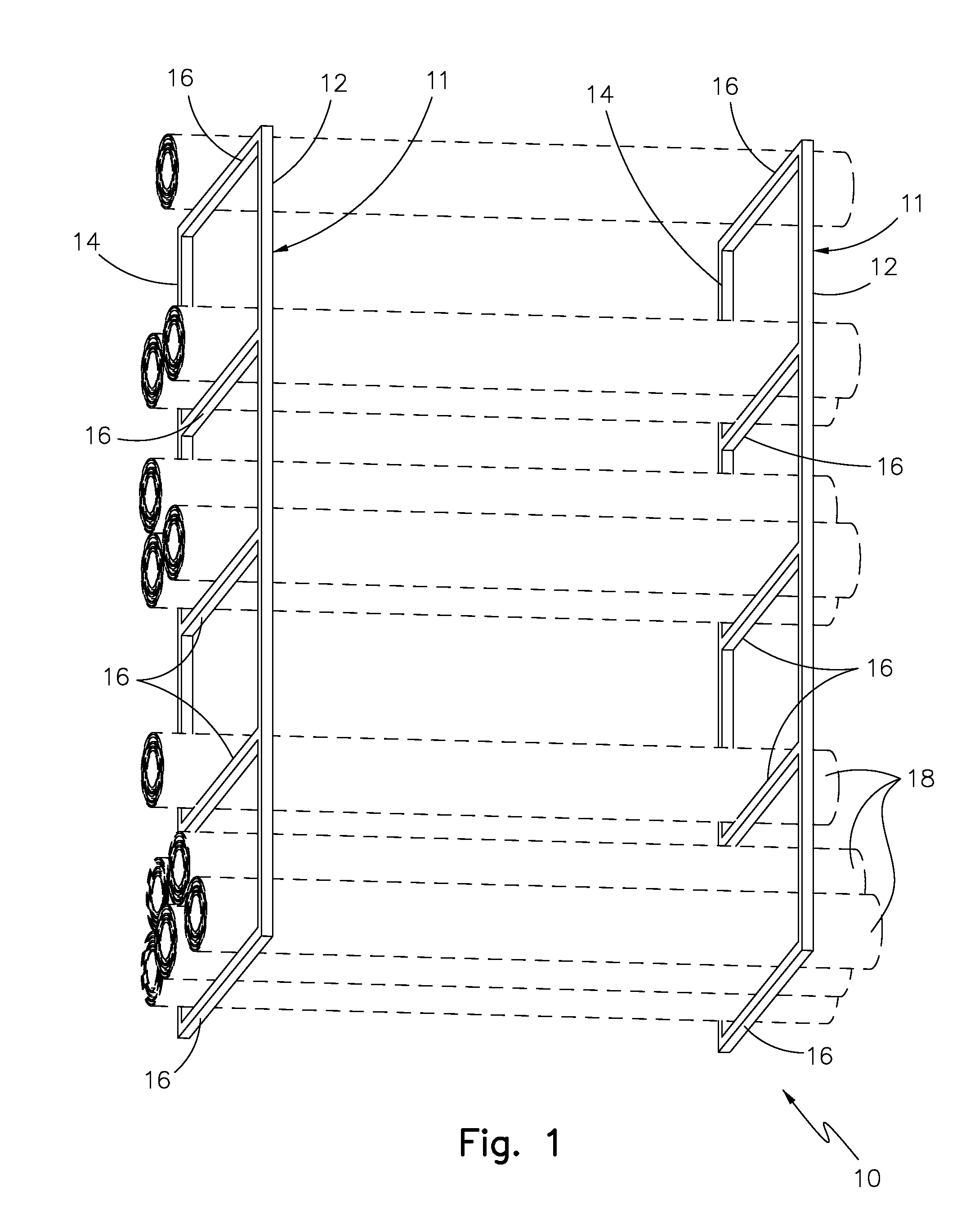
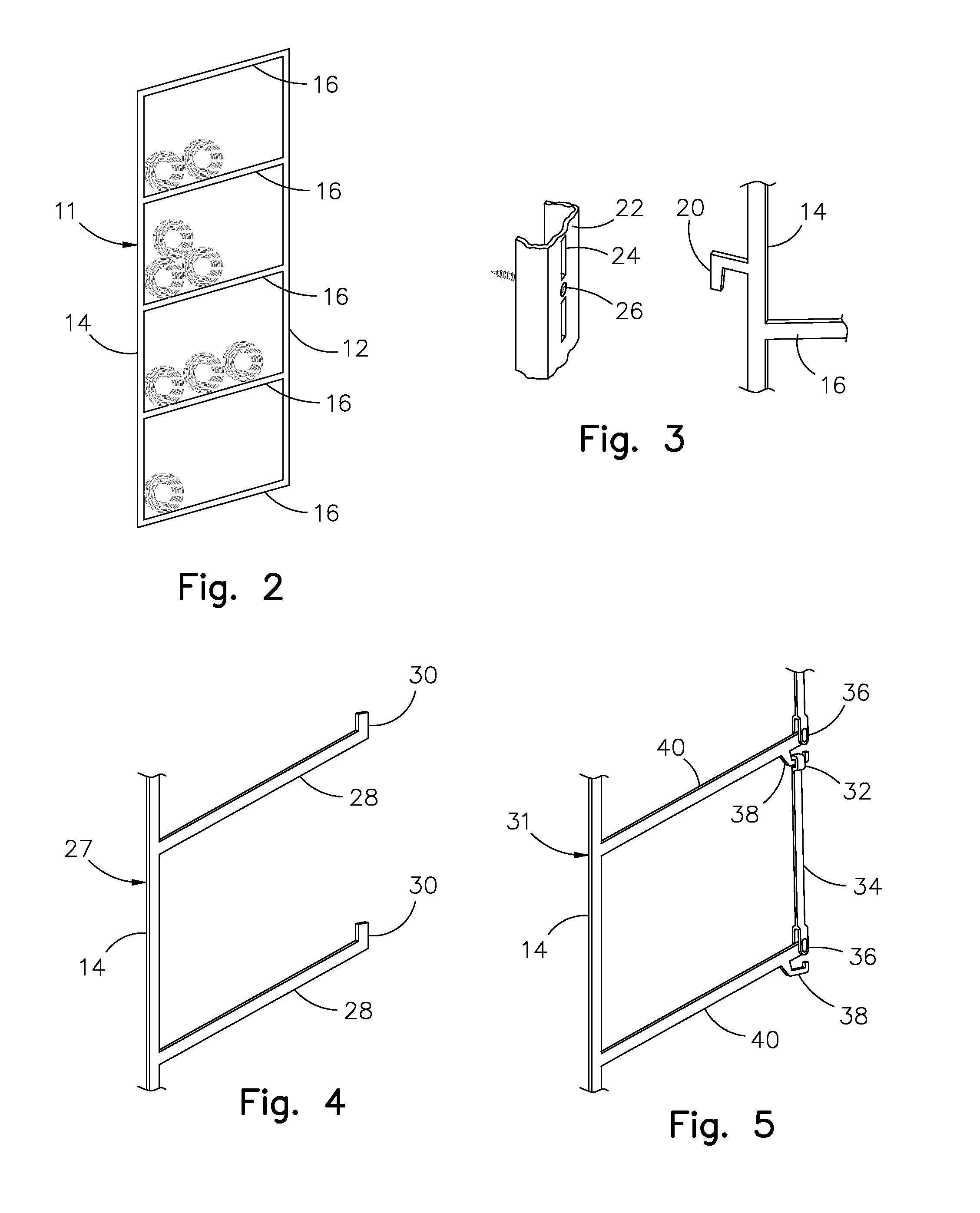
[0021]Referring now to the drawings, where the present invention is generally referred to in FIG. 1 with numeral 10, it can be observed that it basically includes, inter alia, a front frame 12, a rear frame 14 and shelves 16. Rolled plans 18 are shown to demonstrate a potential use of the device. A frame assembly 11 is comprised of a front frame 12, a rear frame 14 and a multiplicity of shelves 16.

[0022]The variation of the angled rolled plan rack as shown in FIGS. 1 and 2 is comprised of at least two frame assemblies 11, one on the right and the other on the left. It is possible that for some applications three, four or more frame assemblies 11 may be used in concert if needed to support additional weight or wider printed media. Each frame assembly 11 has a rear frame 14 that when in use is oriented vertically and is substantially parallel to the front frame 12. On each frame assembly 11 spanning between the rear frame 14 and front frame 12 are a multiplicity of shelves 16. Each of...


PUM


Abstract

A angled rolled plan rack is provided that includes a series of angled shelves supported by a frame that is particularly suited to hold a quantity of rolled large format drawings such as architectural plans, engineering drawings and the like. The shelves are angled toward the rear of the frame so that gravity holds the rolled plans on the rack. A multiplicity of rack assemblies, one on the right and the other on the left, hang on a vertical surface (such as wall) or are placed on a horizontal surface (such as a floor or desk) and complement each other forming a support for rolled plans. This configuration permits the title block on the rolled plans to be easily visible for identification and easy removal of a rolled plan while retaining the ability to store a large number of rolled plans in a compact and efficient form. Variations of the angled rolled plan rack include a closed front, a semi-open front and a gated front and various mounting means.

Description

BACKGROUND OF THE INVENTION[0001]1. Field of the Invention[0002]The present invention relates to storage racks, and more particularly, to a storage rack with angled shelves suited for, large print media, rolls of paper plans or drawings.[0003]2. Description of the Related Art[0004]Several designs for shelving or rack systems have been designed in the past. None of them, however, includes an angled rack that holds numerous large format rolled plans oriented in a manner that allows easy viewing of the label to identify the plans while retaining the ability to easily remove any selected plan without removing other plans held in the rack or other undue difficulty.[0005]Applicant believes that the closest reference corresponds to U.S. Pat. No. 262,556 issued to Bailey. However, it differs from the present invention because the Bailey device is limited to fixed width applications, does not allow for multiple plans to be supported by each shelf, does not have any means to prevent plans fro...

Claims


Application Information

Patent Timeline
Patent Type & Authority Applications(United States)
IPC IPC(8): A47F7/00
CPCA47B95/008B65G1/0442A47F7/175A47B97/00
Inventor GEOFFREY, PAMELA A.
Owner GEOFFREY PAMELA A
Why Eureka
Try Eureka