Failure diagnosis circuit, power supply device, and failure diagnosis method

a failure diagnosis circuit and power supply technology, applied in power supply testing, battery/fuel cell control arrangement, instruments, etc., can solve the problems of high probability and erroneous terminal voltage detection by the voltage detection uni

Inactive Publication Date: 2011-08-18
PANASONIC CORP
View PDF4 Cites 18 Cited by
  • Summary
  • Abstract
  • Description
  • Claims
  • Application Information

AI Technical Summary

Benefits of technology

[0014]It is an object of the present invention to provide a failure diagnosis circuit that can detect a failure of a voltage detection unit that outputs a terminal voltage of an electricity storage unit, without enhancing the deterioration of the electricity storage unit, and also to provide a power supply device and a failure diagnosis method.
[0019]With such a configuration, it is not necessary to charge the electricity storage unit to a level above the usual range of use in order to perform failure diagnosis of the voltage detection circuit, which detects the terminal voltage of the electricity storage unit, in a power supply device including the electricity storage unit. Therefore the failure of the voltage detection unit can be detected without accelerating the deterioration of the electricity storage unit.
[0020]With the abovementioned failure diagnosis circuit, power supply device, and failure diagnosis method, it is not necessary to charge the electricity storage unit to a level above the usual range of use in order to perform failure diagnosis of the voltage detection unit, which detects the terminal voltage of the electricity storage unit. Therefore the failure of the voltage detection unit can be detected without accelerating the deterioration of the electricity storage unit.

Problems solved by technology

Where the variation of the terminal voltage, which is detected by the voltage detection unit, after the charging is stopped by the charging stopping unit differs from the predicted variation when the SOC of the electricity storage unit is at the determination value, it is highly probable that the terminal voltage detected by the voltage detection unit is erroneous.

Method used


Image

  • Failure diagnosis circuit, power supply device, and failure diagnosis method
  • Failure diagnosis circuit, power supply device, and failure diagnosis method
  • Failure diagnosis circuit, power supply device, and failure diagnosis method

Examples


Embodiment Construction

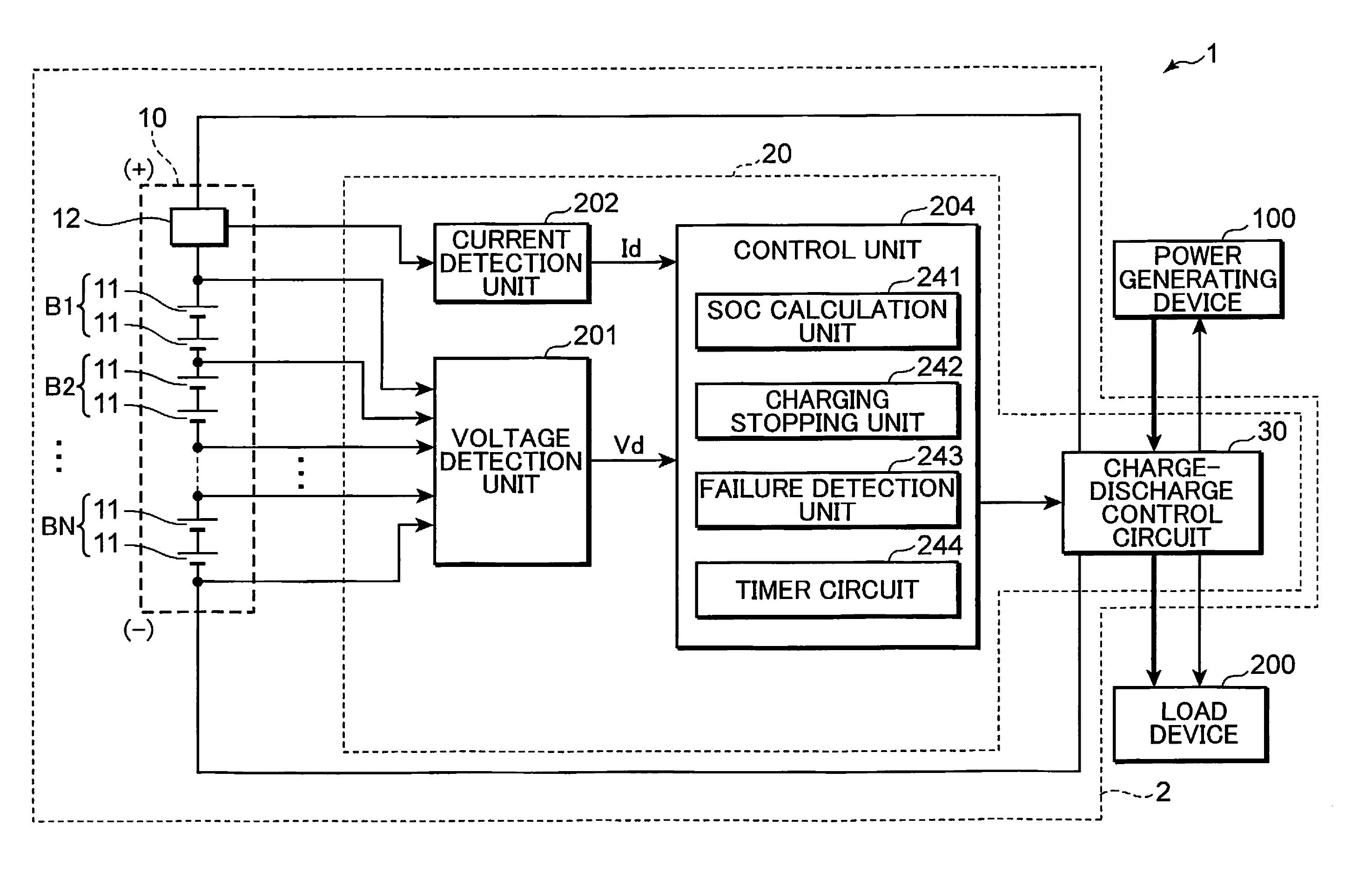
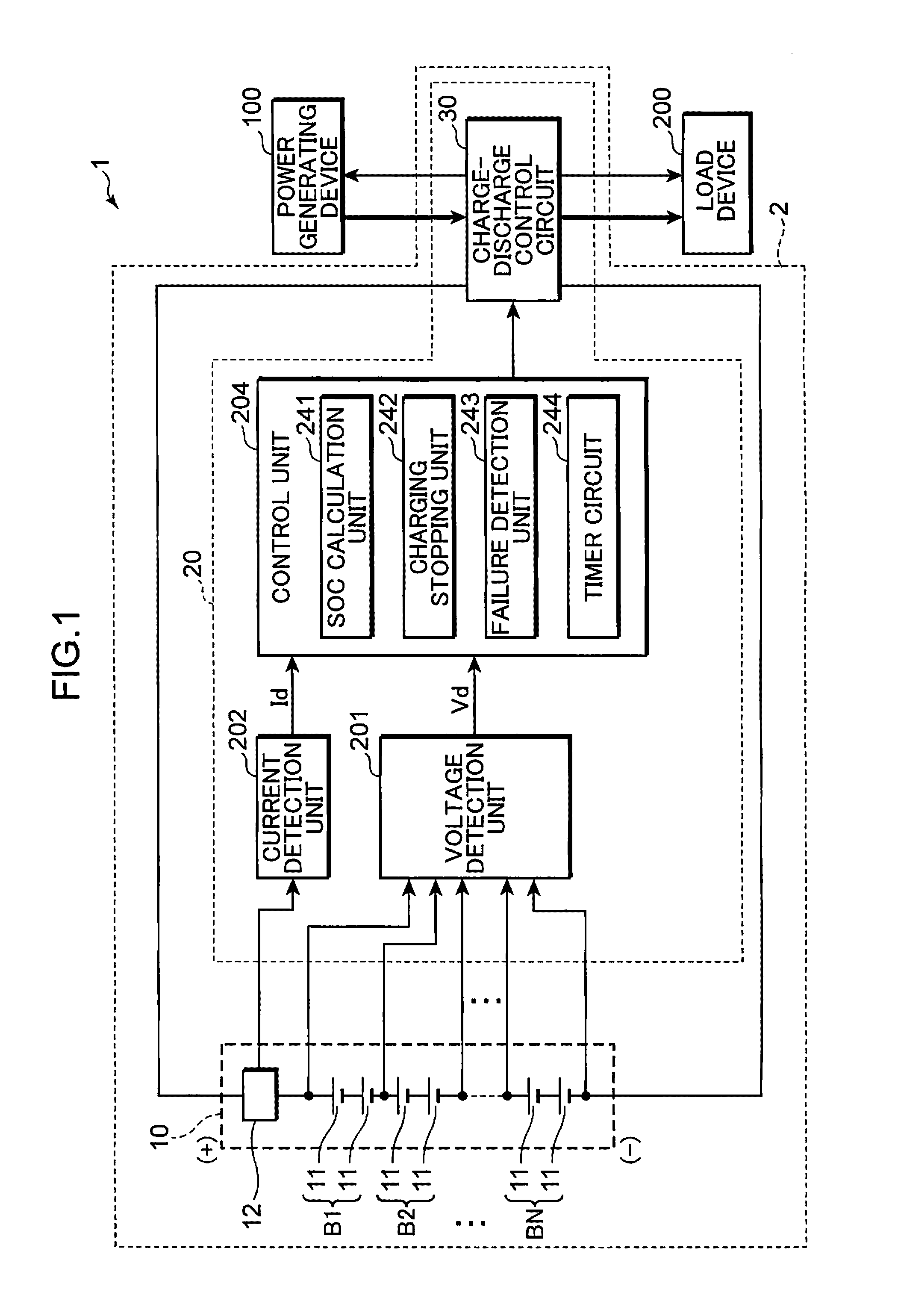
[0024]The embodiments of the present invention will be described below with reference to the appended drawings. In the drawings, the components denoted by like reference numerals represent like components and the explanation thereof is herein omitted. FIG. 1 is a block diagram illustrating an example of a configuration of a failure diagnosis circuit using the failure diagnosis method according to one embodiment of the present invention, a power supply device including the failure diagnosis circuit, and a power supply system.

[0025]The power supply system 1 shown in FIG. 1 is constituted by a power supply device 2, a power generating device 100, and a load device 200. A variety of power supply devices, for example a battery pack, an uninterruptable power supply device, an electricity storage device for power adjustment that stores extra power of a power generating device using an engine as a drive source and a power generating device using natural energy, and a load leveling power sou...


PUM


Abstract

A failure diagnosis circuit is provided with: a voltage detection unit that detects a terminal voltage of an electricity storage unit; a current detection unit that detects a current flowing in the electricity storage unit; a SOC calculation unit that calculates a SOC of the electricity storage unit on the basis of the current detected by the current detection unit; a charging stopping unit that stops charging of the electricity storage unit when the SOC calculated by the SOC calculation unit reaches a preset determination value; and a failure detection unit that determines that a failure has occurred in the voltage detection unit when a variation of the terminal voltage, which is detected by the voltage detection unit, after the charging is stopped by the charging stopping unit differs from a predicted variation when the SOC of the electricity storage unit is at the determination value.

Description

TECHNICAL FIELD[0001]The present invention relates to a failure diagnosis method for detecting a failure of a voltage detection unit that detects a terminal voltage of an electricity storage unit, a failure diagnosis circuit, and a power supply device using the same.BACKGROUND ART[0002]Electricity storage devices using electricity storage units have been widely used in recent years as power supply systems in combinations with solar cells or power generating devices. Power generating devices are driven by natural energy such as wind power of water power or artificial power such as that of an internal combustion engine. In a power supply system incorporating such an electricity storage device, excess power is accumulated and stored in the electricity storage device and this power is supplied from the electricity storage device when it is required by a load device, thereby increasing the energy efficiency.[0003]A solar power generating system is an example of such system. When the quan...

Claims


Application Information

Patent Timeline
Patent Type & Authority Applications(United States)
IPC IPC(8): G01R31/40
CPCB60L3/0046B60L11/1861G01R19/0084G01R31/3606G01R31/3658G01R35/00Y02T10/7055H01M10/482H02J7/0021Y02T10/7005Y02T10/7044Y02T10/705H01M10/46G01R31/382G01R31/396B60L58/13B60L58/15B60L58/14B60L58/18Y02T10/70Y02E60/10H02J7/0013H02J7/005
Inventor IIDA, TAKUMA
Owner PANASONIC CORP
Why Eureka
Try Eureka