Liquid ejection device

Active Publication Date: 2011-08-18
SEIKO EPSON CORP
View PDF4 Cites 10 Cited by
  • Summary
  • Abstract
  • Description
  • Claims
  • Application Information

AI Technical Summary

Benefits of technology

[0027]According to this configuration, because the pressure in the inner space has already been increased when the cap member is separated from the nozzle formation surface, the pressure in the

Problems solved by technology

Because the water content of the ink tends to evaporate through openings of the nozzles, the viscosity of the ink in the nozzles increases and hence the nozzles are easily clogged.
The following problem may however occur when the sealing cap is removed and printing is initiated.
To prevent the print

Method used


Image

  • Liquid ejection device
  • Liquid ejection device
  • Liquid ejection device

Examples


first embodiment

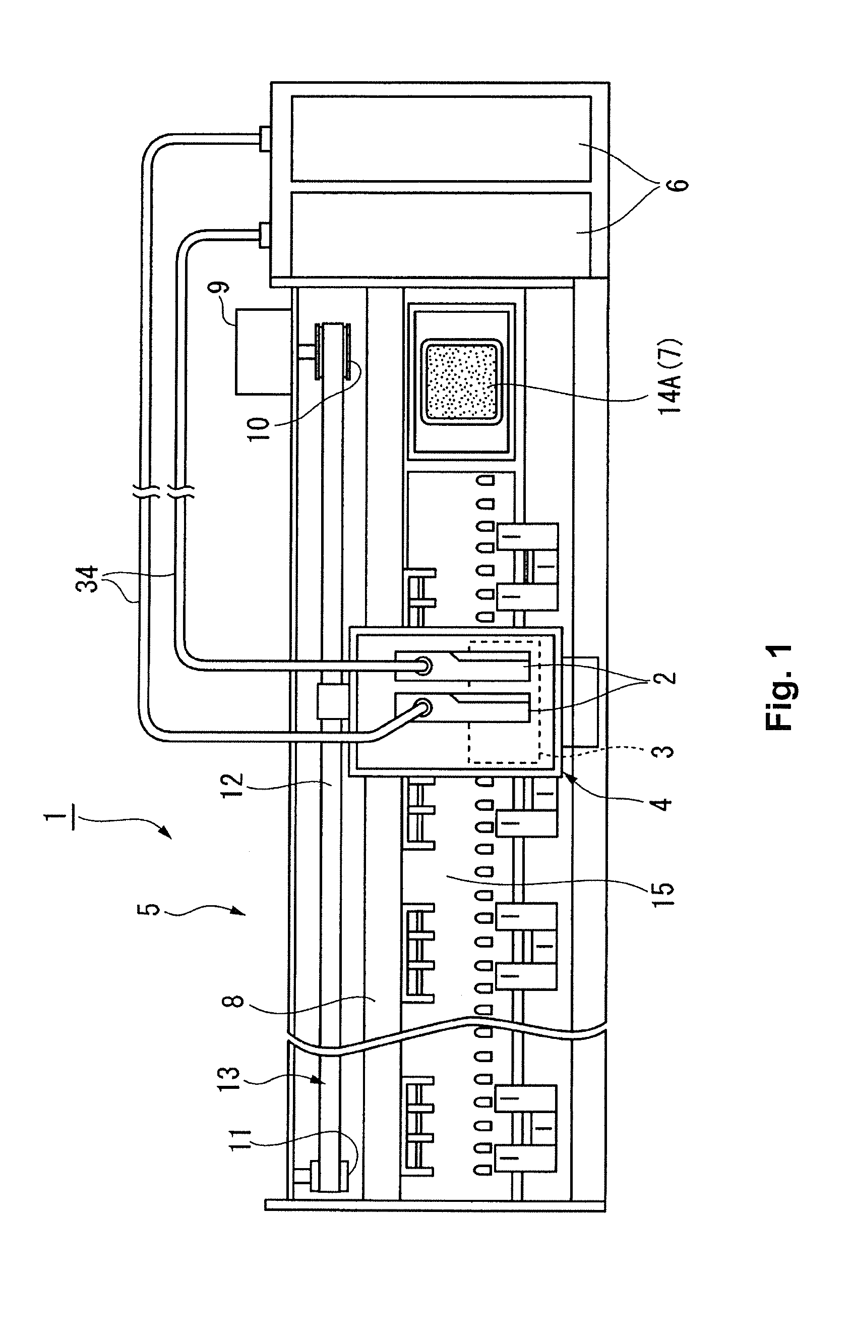
[0036]A liquid ejection device according to a first embodiment of the invention will be described below with reference to FIGS. 1 to 4. In all the following drawings, the dimensions and proportions of components differ as required for ease of illustration.

[0037]FIG. 1 is a partial view showing a schematic configuration of a printer (liquid ejection device) 1 according to the first embodiment of the invention. The printer 1 generally has a carriage 4 in which sub-tanks 2 and a recording head 3 are incorporated, and a printer body 5. The printer body 5 is provided with a carriage translation mechanism 13 that translates the carriage 4 in reciprocating motion, a sheet feed mechanism that transports a recording sheet (not shown), a capping mechanism 14A used to clean or otherwise treat the recording head (liquid ejection head) 3, and ink cartridges 6 that store ink supplied to the recording head 3 through supply tubes 34.

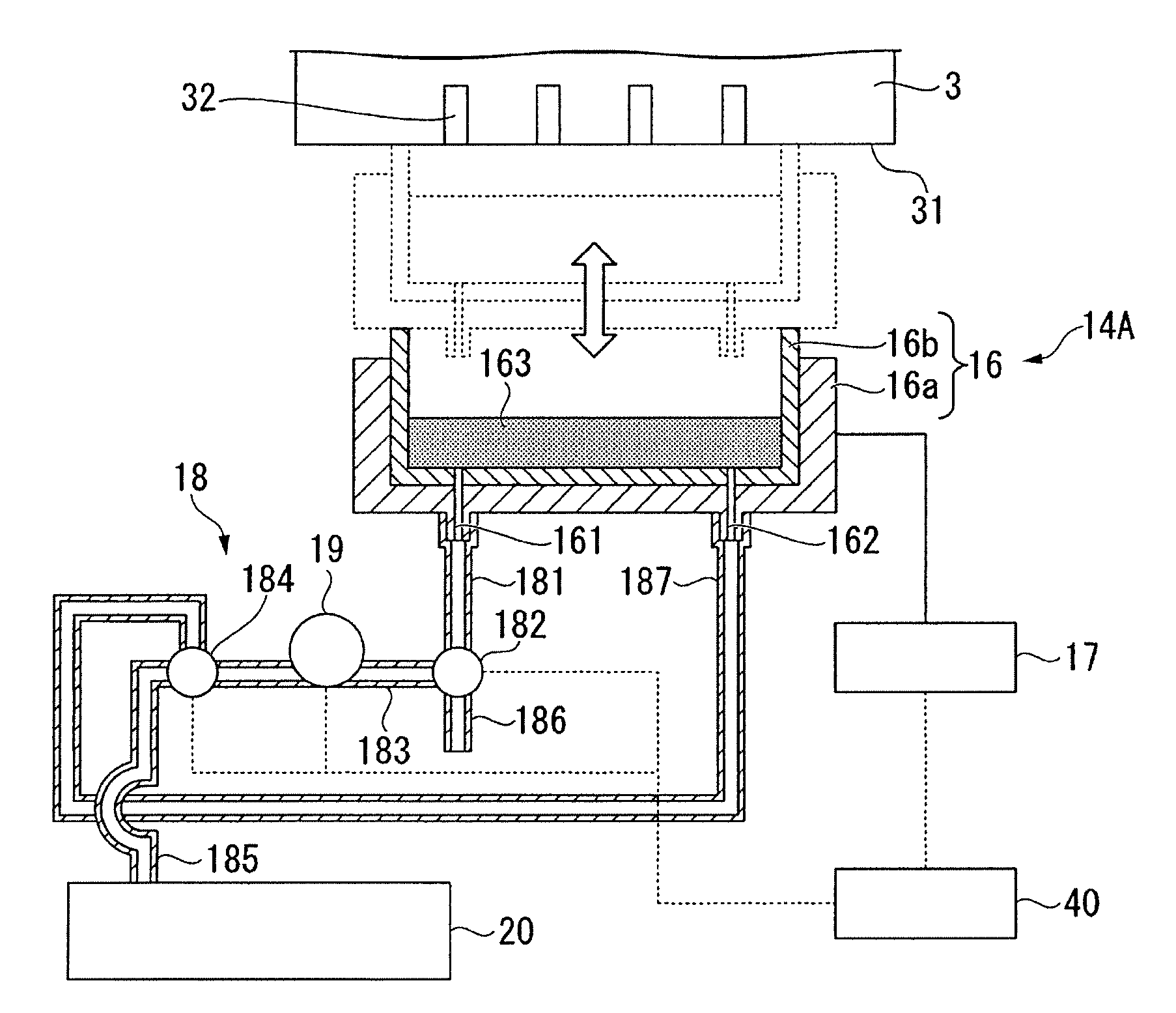
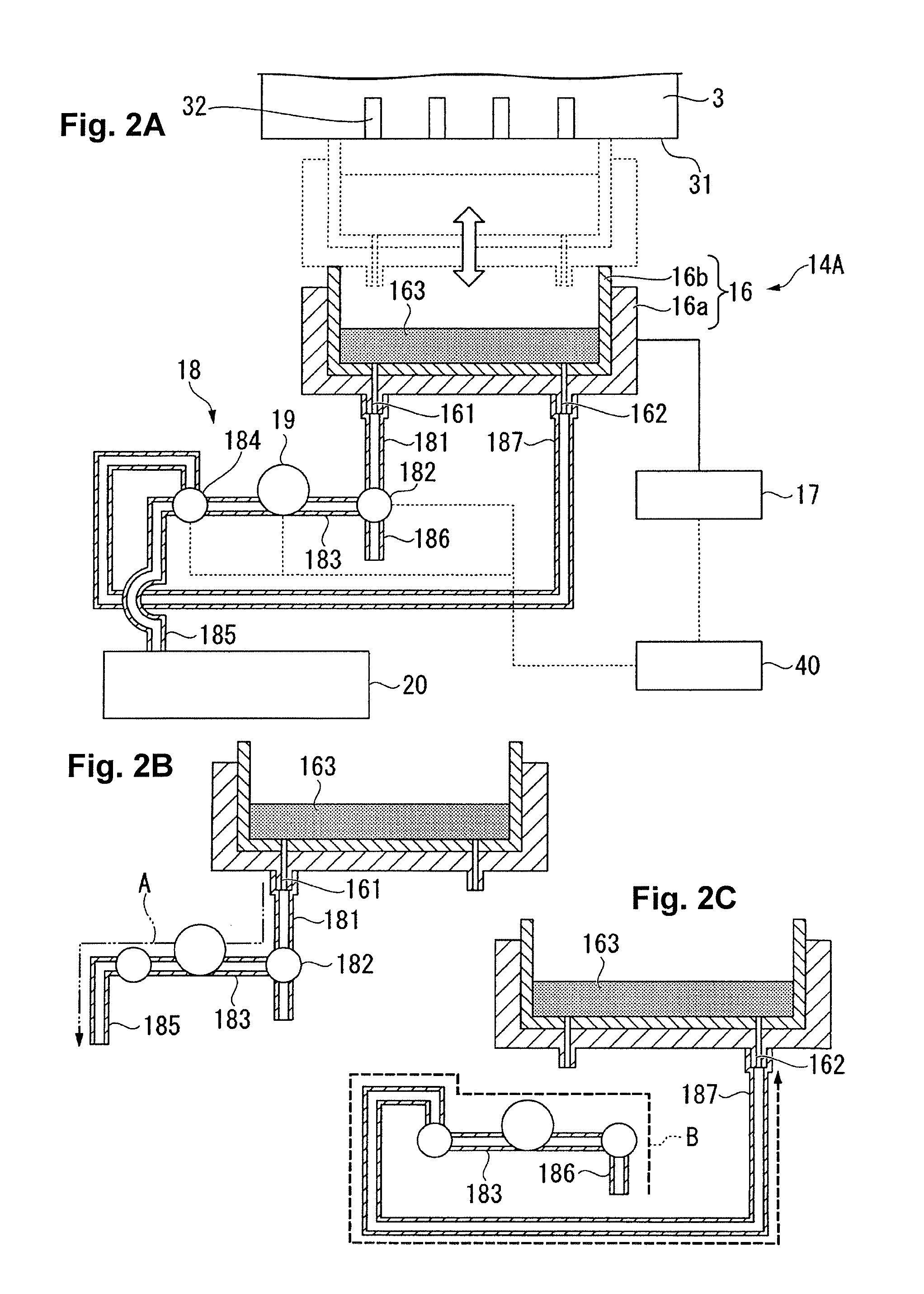
[0038]The capping mechanism 14A includes an ink droplet sensor 7 c...

second embodiment

[0062]FIG. 5 is a descriptive diagram of a capping mechanism 14C provided in a printer according to a second embodiment of the invention. The capping mechanism 14C provided in the printer of the present embodiment is partly the same as the capping mechanism 14A provided in the printer of the first embodiment. They differ from each other in that the capping mechanism 14A increases the pressure in the inner space S1 by delivering air into the cap 16, whereas the capping mechanism 14C increases the pressure in the inner space S1 by heating gas in the inner space S1 to expand the gas. The components in the present embodiment that are common to those in the first embodiment have the identical reference numerals, and no description of these components will be made in detail.

[0063]As shown in FIG. 5, the capping mechanism 14C includes a pipe 18C which is connected to the ink discharge port 161 provided through the bottom of the cap 16 and through which waste ink flows into a waste liquid t...

third embodiment

[0067]FIGS. 6A and 6B are descriptive diagrams of a capping mechanism 14D provided in a printer according to a third embodiment of the invention. The capping mechanism 14D provided in the printer of the present embodiment is partly the same as the capping mechanism 14A provided in the printer of the first embodiment. In the capping mechanism 14D, the capacity of the cap can be changed in order to change the volume of the inner space S1, thereby increasing the pressure in the inner space S1.

[0068]As shown in FIGS. 6A and 6B, a cap 26 provided in the capping mechanism 14D has a tubular cap side portion 261 that forms the side surface of the cap 26 and a cap bottom portion (capacity-changing unit, pressurizing unit) 262 that forms the bottom of the cap 26, and the cap bottom portion 262 fits into the cap side portion 261. A drive mechanism (not shown) can move the cap bottom portion 262 upward and downward inside the cap side portion 261.

[0069]The cap side portion 261 includes a cap ho...


PUM


Abstract

A liquid ejection device includes a liquid ejection head and a capping mechanism. The liquid ejection head includes nozzles for ejecting a liquid. The capping mechanism covers the nozzles and receiving the liquid, the capping mechanism being selectively disposed in a contacting state in which the capping mechanism contacts with a nozzle formation surface of the liquid ejection head or in a separated state in which the capping mechanism is separated from the nozzle formation surface. The capping mechanism includes a cap member forming a space in which openings of the nozzles are hermetically sealed in the contacting state, and a pressurizing unit configured to increase pressure in an inner space surrounded by the nozzle formation surface and an inner surface of the cap member.

Description

CROSS-REFERENCE TO RELATED APPLICATIONS[0001]This application claims priority to Japanese Patent Application No. 2010-029849 filed on Feb. 15, 2010. The entire disclosure of Japanese Patent Application No. 2010-029849 is hereby incorporated herein by reference.BACKGROUND[0002]1. Technical Field[0003]The present invention relates to a liquid ejection device.[0004]2. Related Art[0005]An inkjet printer (hereinafter referred to as a “printer”), which is one type of liquid ejection device, performs printing by ejecting ink (liquid) onto a recording medium through nozzles formed in a nozzle formation surface of a recording head (liquid ejection head) incorporated in a carriage.[0006]Because the water content of the ink tends to evaporate through openings of the nozzles, the viscosity of the ink in the nozzles increases and hence the nozzles are easily clogged. A printer is typically designed to prevent the nozzles from being clogged by performing a maintenance step (cleaning, flushing, or...

Claims


Application Information

Patent Timeline
IPC IPC(8): B41J2/165
CPCB41J2/16526B41J2/16508
Inventor SHIMAZAKI, JUN
Owner SEIKO EPSON CORP
Why Eureka
Try Eureka