Single-transducer, three-dimensional laser imaging system and method

a laser imaging system and single-transducer technology, applied in the field of single-transducer, three-dimensional laser imaging system and method, can solve the problems of difficult array arrangement of sensitive detectors with lower timing jitter, often limited range resolution, etc., to achieve small timing jitter, eliminate or reduce the limit of range resolution, the effect of improving range resolution

Active Publication Date: 2011-08-18
MASSACHUSETTS INST OF TECH
View PDF4 Cites 32 Cited by
  • Summary
  • Abstract
  • Description
  • Claims
  • Application Information

AI Technical Summary

Benefits of technology

[0006]Because example systems require only one transducer, the transducer can be chosen to have as small a timing jitter as is practical, eliminating or lowering limits on range resolution. The use of a single photon-counting transducer also enables detection of scattered or reflected returns that are too weak to be detected with conventional detector arrays. In addition, mapping center frequency to spatial location does not require moving parts, such as galvo-scanning mirrors, or active beam-steering components, such as acousto-optic and electro-optic deflectors, unlike other beam steering techniques. These attributes give imagers that map pulses of different center frequencies to different spatial locations the ability to operate with better range resolution, detect weaker signals, and scan more quickly than other 3D imagers.

Problems solved by technology

The range resolution is often limited by the precision of the time-of-flight measurement, which depends on the timing jitter of the transducer that detects the scattered or returned radiation.
Unfortunately, sensitive detectors with lower timing jitter cannot be easily arranged into arrays.

Method used


Image

  • Single-transducer, three-dimensional laser imaging system and method
  • Single-transducer, three-dimensional laser imaging system and method
  • Single-transducer, three-dimensional laser imaging system and method

Examples


Embodiment Construction

[0014]A description of example embodiments of the invention follows.

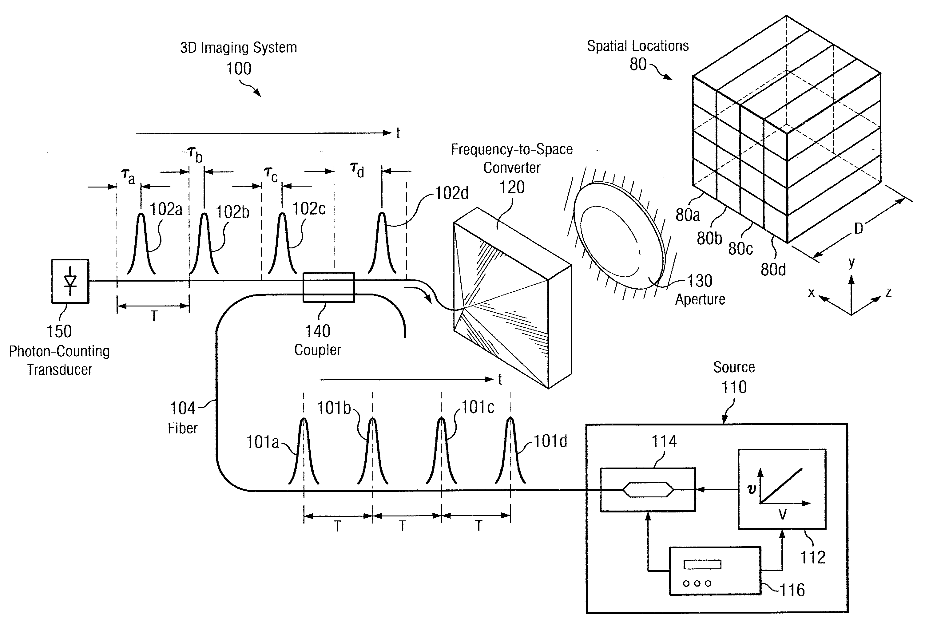
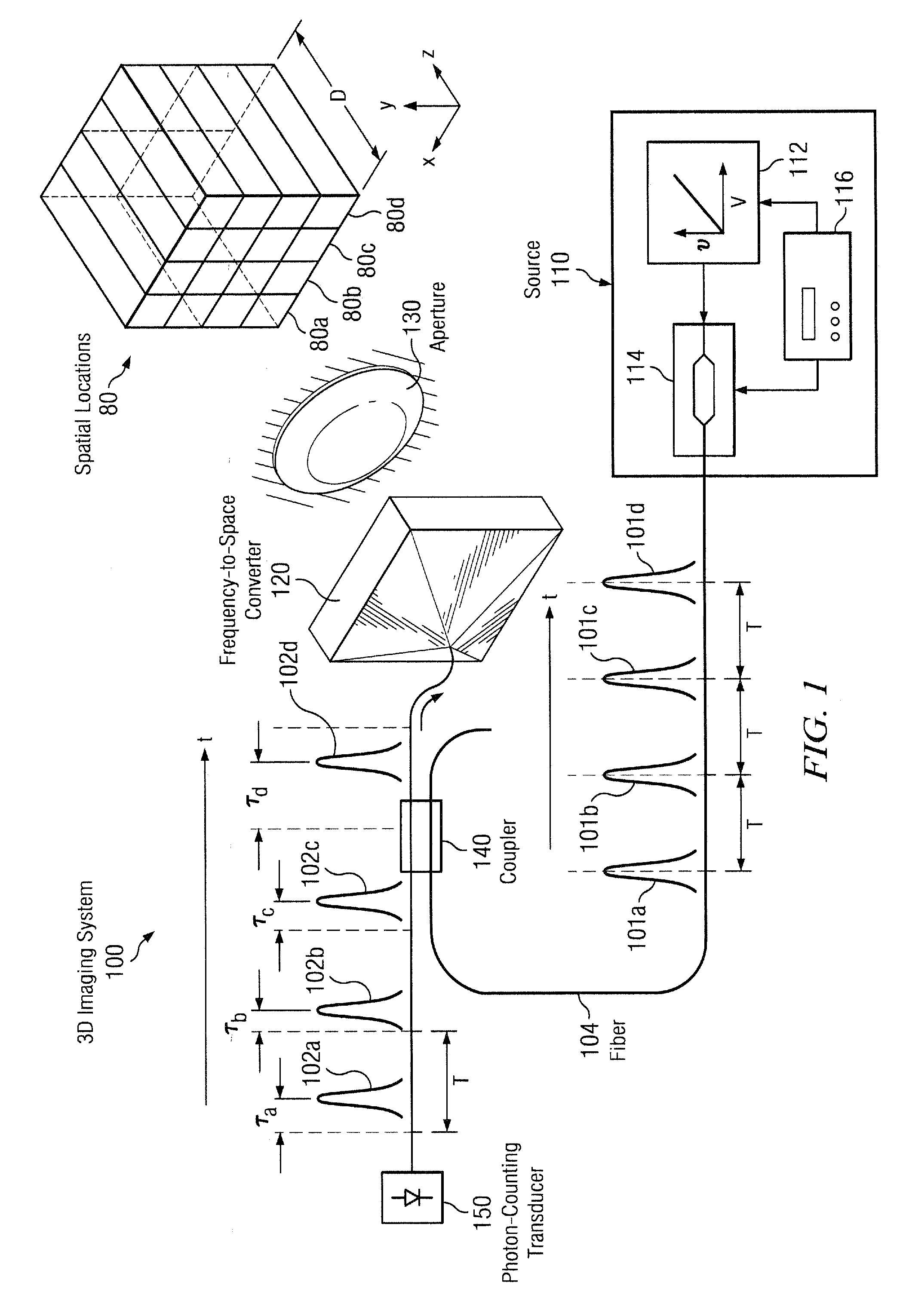
[0015]FIG. 1 shows a monostatic three-dimensional (3D) imaging system 100 that maps pulses 101a-101d (collectively, pulses 101) to corresponding spatial locations 80a-80d (collectively, spatial locations 80) based on the center frequencies of the pulses 101. For clarity, only the first row of spatial locations 80a-80d and the corresponding pulses 101a-101d are labeled in FIG. 1. The pulses 101 are emitted by a source 110 that includes a tunable laser 112 coupled to a pulse carver 114. A waveform generator 116 applies a voltage to the tunable laser 112, causing the output of the laser 112 to change in frequency. For example, the laser frequency may be “chirped,” or swept from a low frequency to a high frequency (or vice versa) by applying an increasing voltage to the laser 112. At the same time, the waveform generator 114 applies a voltage to the pulse carver 114, which may include a fiber-coupled Mach-Zehnder modula...


PUM


Abstract

Disclosed herein are a system and method for three-dimensional imaging using a single transducer. A laser in a transmitter emits a sequence of short pulses, each of which is at a different center wavelength (frequency). A dispersive element in the transmitter spatially separates the pulses according to wavelength, with different pulses mapped to different spatial locations in a target volume via a lens. The pulses travel to the target, which scatters or back-reflects the pulses towards the dispersive element via the lens. The lens collects the returned pulses and transmits them to a single transducer via the dispersive element. The transducer measures the time of arrival for each returned pulse. Because the arrival time depends on the range to the object in the portion of the target illuminated by the corresponding emitted pulse, the measured arrival time can be used to reconstruct a 3D (angle-angle-range) image of the object.

Description

GOVERNMENT SUPPORT[0001]The invention was supported, in whole or in part, by a grant FA8721-05-C-0002 from the U.S. Air Force. The Government has certain rights in the invention.BACKGROUND OF THE INVENTION[0002]Three-dimensional (3D) imaging typically involves sweeping or scanning a beam across a volume and measuring the radiation reflected or scattered by an object in the volume. The angle or position of the beam corresponds to the object's transverse (x and y) coordinates, and the delay between the emission of the beam and the arrival of the reflected or scattered radiation, or time-of-flight, indicates the object's range, or location in z. The returned radiation is typically sensed with a detector array, such as an array of avalanche photodiodes, and used to create a 3D image of the scene being illuminated. In general, the range of the system depends on the sensitivity of the detector array, with better sensitivity giving better range performance for a given transmitter power and...

Claims


Application Information

Patent Timeline
Patent Type & Authority Applications(United States)
IPC IPC(8): G01B11/28
CPCG01S17/89
Inventor ROBINSON, BRYAN S.BOROSON, DON M.ALBOTA, MARIUS A.
Owner MASSACHUSETTS INST OF TECH
Why Eureka
Try Eureka