Methods for forming index guided vertical cavity surface emitting lasers

a laser and vertical cavity technology, applied in semiconductor lasers, laser details, electrical equipment, etc., can solve the problems of large contact area that cannot be manufactured with low resistance, lack of index refraction difference in the lateral direction of planar proton implanted vcsels to provide good optical confinement, and poor optical confinement performance, so as to improve current confinement, improve optical confinement and proton implantation performance, the effect of minimizing thermal lensing effects

Inactive Publication Date: 2005-02-08
LUMENTUM OPERATIONS LLC
View PDF179 Cites 21 Cited by
  • Summary
  • Abstract
  • Description
  • Claims
  • Application Information

AI Technical Summary

Benefits of technology

The apparatus and manufacture of a planar index guided vertical cavity surface emitting laser (VCSEL) is provided. Planar index guided vertical cavity surface emitting laser (PIG VCSEL) utilizes index guiding to provide improved optical confinement and proton implantation to improve current confinement. Index guiding is achieved by etching a plurality of index guide openings (holes, partial ridges or other shapes) into a p-DBR mirror around the desired optical confinement region. The index guiding may be adjusted by varying the etched volume and depth of index guide openings (holes, partial ridges, or other shapes). The degree of index guiding is achieved by controlling the etching profile and etching depth. The degree of current confinement is achieved by controlling the implant depth and the overlap between the implant portion and etching portion. Index guiding minimizes thermal lensing effects, and thus provides a smaller turn-on delay and a smaller timing jitter. The planar index guided (PIG) VCSELs provides good optical mode confinement and current confinement, and thus lower threshold current, allowing low power consumption and higher reliability. The top contact (p-metal) surface area is increased in the PIG VCSEL thereby lowering contact and device resistance to improve VCSEL performance further. Parasitic capacitance is also reduced by providing the increased top contact surface area to provide improved high speed operation. The PIG VCSEL is a planarized device having a planar top surface for ease of manufacture. The simple methods of manufacturing PIG VCSELs are disclosed herein.

Problems solved by technology

As a result, a large contact area can be manufactured with low resistance.
However, planar proton implanted VCSELs lack sufficient index refraction difference in the lateral direction to provide good optical confinement.
These methods of optical confinement provide poor performance and result in planar proton implanted VCSELs having a high threshold current, large turn-on delay and large timing jitter.
The planar proton implanted VCSEL having a large turn-on delay and a large timing jitter makes it unsuitable for high speed applications beyond 2.5 Gbps.
The ridge waveguide proton implanted VCSEL provides a lower threshold current than a planar proton implanted VCSEL and thus potentially longer operational lifetime.
However, ridge waveguide VCSELS are difficult to manufacture because of their nonplanar surface.
The top surface metalization of a ridge waveguide VSCEL is particularly difficult to manufacture.
A disadvantage to ridge waveguide VCSELs is that the heat dissipation is poor resulting in a thermal resistance typically 50% greater than that of planar proton implanted VCSELs.
Large device resistances result in large RC time constants, ultimately limiting the device from high speed applications.
Oxide confined VCSELs have lower threshold currents due to good current confinement and lower resistance that allows for high speed operation.
Disadvantages associated with the oxidized VCSEL technology are difficult manufacturability (i.e., low yield) and poor uniformity, consistency, and reliability.
Generally, it is desirable to avoid oxidizing a material within a VSCEL because it creates lattice defects that will grow and eventually degrades VCSEL device performance.
In addition, stresses caused by the volume change after material oxidation accelerates VCSEL device degradation.

Method used


Image

  • Methods for forming index guided vertical cavity surface emitting lasers
  • Methods for forming index guided vertical cavity surface emitting lasers
  • Methods for forming index guided vertical cavity surface emitting lasers

Examples


Embodiment Construction

In the following detailed description of the present invention, numerous specific details are set forth in order to provide a thorough understanding of the present invention. However, it will be obvious to one skilled in the art that the present invention may be practiced without these specific details. In other instances well known methods, procedures, components, and circuits have not been described in detail so as not to unnecessarily obscure aspects of the present invention.

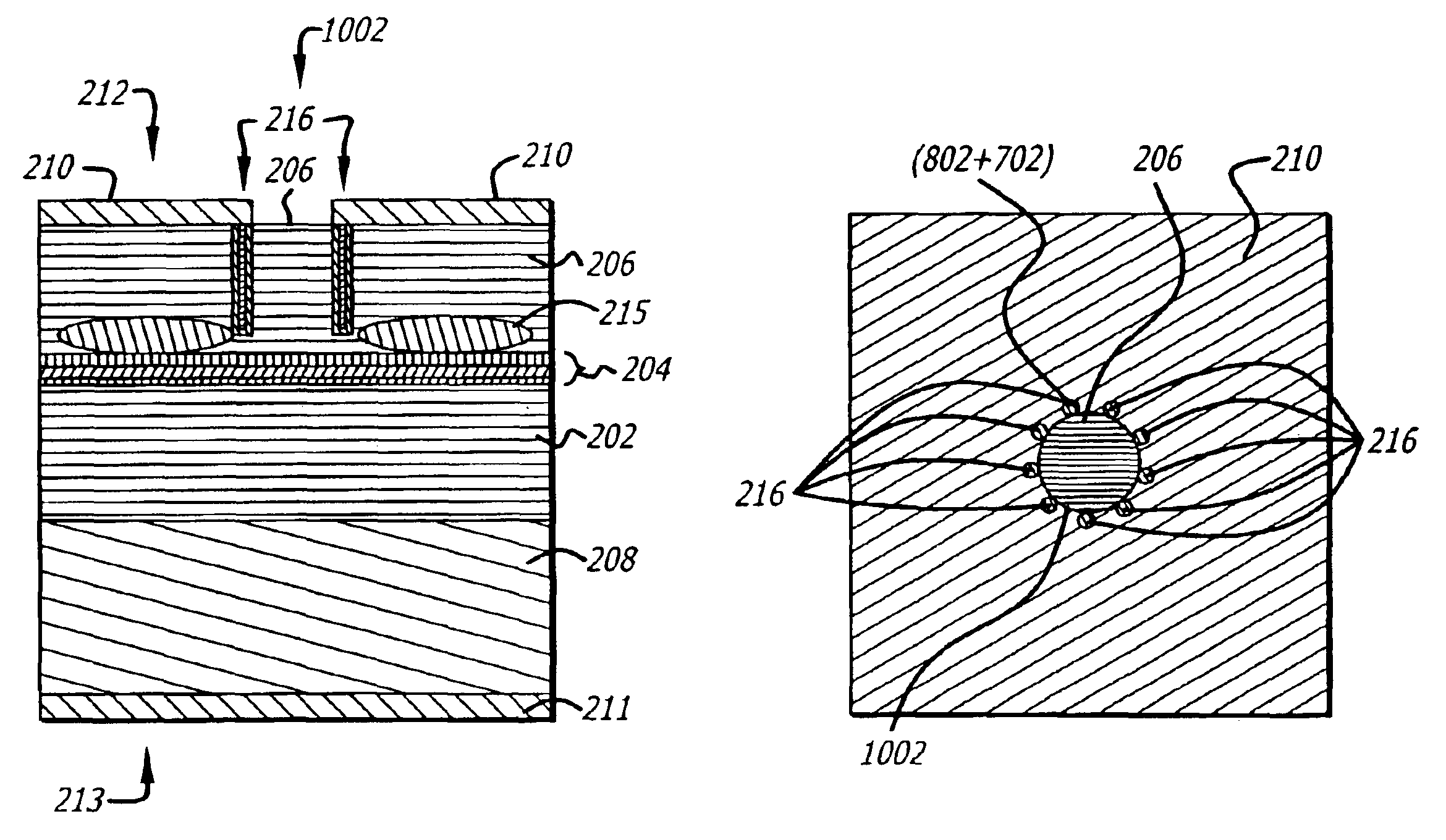
A planar index guided vertical cavity surface emitting laser (PIG VCSEL) is provided by the present invention offering improved performance over prior art VCSELs in order to improve communication systems. The PIG VCSEL is substantially planar for ease of manufacturing and provides current confinement by proton implantation and optical confinement by etching holes or partial ridges within the VCSEL surrounding the optical confinement region for index guiding. The desired degree of index guiding is achieved by ...


PUM


Abstract

Planar index guided vertical cavity surface emitting laser (PIG VCSEL) utilizes index guiding to provide improved optical confinement and proton implantation to improve current confinement. Index guiding is achieved by etching index guide openings (holes or partial ridges) around the optical confinement region and may be adjusted by varying the etched volume of the index guide openings (holes and partial ridges). The top contact surface area is increased in the PIG VCSEL thereby lowering contact and device resistance to improve VCSEL performance further. The PIG VCSEL is a substantially planarized device for ease of manufacture.

Description

FIELD OF THE INVENTIONThe present invention relates generally to semiconductor lasers. More particularly, the present invention relates to vertical cavity surface emitting lasers (VCSELs).BACKGROUND OF THE INVENTIONSemiconductor lasers have become more important. One of the more important applications of semiconductor lasers is in communication systems where fiber optic communication media is employed. With growth in electronic communication, communication speed has become more important in order to increase data bandwidth in electronic communication systems. Improved semiconductor lasers can play a vital roll in increasing data bandwidth in communication systems using fiber optic communication media.The operation of basic semiconductor lasers is well known. Semiconductor lasers can be categorized as surface emitting or edge emitting depending upon where laser light is emitted. They may also be classified by the type of semiconductor junctions used such as heterojunction or homojunc...

Claims


Application Information

Patent Timeline
Patent Type & Authority Patents(United States)
IPC IPC(8): H01S5/00H01S5/183H01S5/20
CPCH01S5/18316H01S5/2063H01S5/18333
Inventor LEE, HSING-CHUNGCHUI, LIEW-CHUANG
Owner LUMENTUM OPERATIONS LLC
Why Eureka
Try Eureka