Display device

a display device and display screen technology, applied in the field of display devices, can solve problems such as attracting many customers, and achieve the effects of fewer components, fewer processes, and reduced costs

Inactive Publication Date: 2011-08-18
LG ELECTRONICS INC
View PDF2 Cites 1 Cited by
  • Summary
  • Abstract
  • Description
  • Claims
  • Application Information

AI Technical Summary

Benefits of technology

[0013]According to the embodiments, since the back cover is in direct contact with the upper glass of the plasma display module and fixed to the plasma display module, the display device can be manufactured with fewer components and lower costs through fewer processes.
[0014]Furthermore, since the upper glass of the plasma display module forms the entire front exterior of the display device, the front exterior of the display device may seem neat, and the screen of the display device may seem bigger.
[0015]In addition, since the back cover is grounded on the upper glass through direct contact with the upper glass, the number of connections necessary for electric grounding of the display device can be reduced, and thus the grounding efficiency of the display device can be improved.

Problems solved by technology

Such flat display devices occupy less space owing to its small volume and are light and easy-to-handle, thus attracting many customers.

Method used


Image

  • Display device
  • Display device
  • Display device

Examples


second embodiment

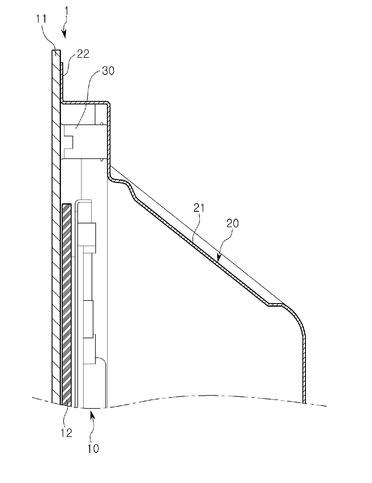
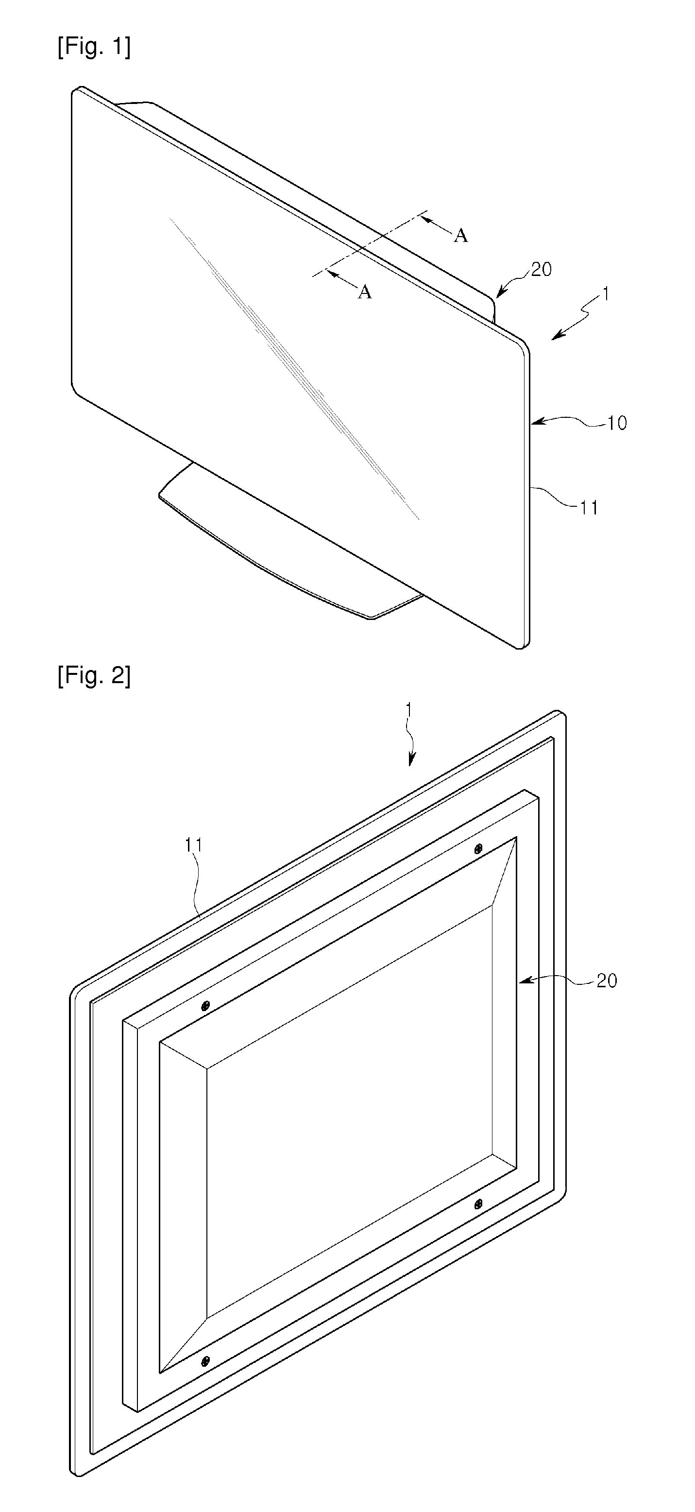
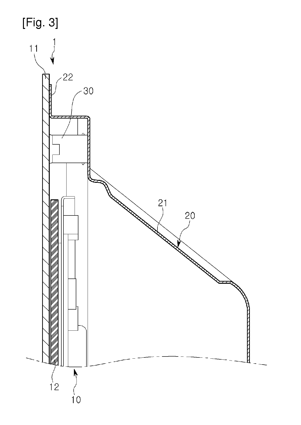
[0050]FIG. 4 is a sectional view taken long line A-A of FIG. 1, according to a

first embodiment

[0051]The current embodiment is the same as the first embodiment except for a grounding member disposed between the upper glass and the back cover. Thus, in the following description of the current embodiment, the characteristic part will be only described.

[0052]Referring to FIG. 4, in the current embodiment, a grounding member 40 is provided on the backside of the upper glass 11. The grounding member 40 is fixed to four backside edge portions of the upper glass 11. The grounding member 40 may be fixed to the upper glass 11 using an adhesive member (e.g., a double-sided tape) or an adhesive.

[0053]The extension part 22 of the back cover 20 is in contact with the grounding member 40.

[0054]The grounding member 40 may be formed of a conductive material such as aluminum or copper. The grounding member 40 may be elastic. For example, the grounding member 40 may be configured by an elastic member (e.g., sponge) and a conductive member (e.g., an aluminum member) surrounding the elastic memb...

third embodiment

[0059]FIG. 5 is a rear perspective view illustrating a display device and FIG. 6 is a sectional view taken along line B-B of FIG. 5.

[0060]The current embodiment is the same as the first embodiment except for a method of fixing a plasma display module and a back cover. Thus, in the following description, the characteristic feature will be only described.

[0061]Referring to FIGS. 5 and 6, in the current embodiment, an upper glass 11 includes a coupling member 50 for coupling with a back cover 20. The coupling member 50 may be fixed to the backside of the upper glass 11 by using an adhesive member (not shown) or an adhesive (not shown).

[0062]The coupling member 50 includes upper and lower coupling members 51 and 52 disposed at upper and lower backside edge portions of the upper glass 11, and a lateral coupling member 53 disposed at a right backside edge portion of the upper glass 11 and connected to the upper and lower coupling members 51 and 52. In the current embodiment, the lateral ...


PUM


Abstract

A display device is provided. The display device includes a display module including an upper glass which forms a front exterior of the display device and is used for displaying images, and a back cover making contact with the upper glass and covering the display module.

Description

TECHNICAL FIELD[0001]The present disclosure relates to a display device.[0002]1. Background Art[0003]Generally, display devices are used to display images. Recently, many display devices having a two-dimensional flat shape have been introduced into the market. Such flat display devices occupy less space owing to its small volume and are light and easy-to-handle, thus attracting many customers.[0004]Such a display device may include a display module for displaying images. Examples of the display module include a plasma display module.[0005]The plasma display module is operated by using light emitted from a fluorescent material excited by ultraviolet rays generated by gas-discharging.[0006]In a typical display device, the plasma display module is protected by front and rear cabinets. That is, the front cabinet forms the front exterior of the display device and covers the plasma display module.[0007]2. Disclosure of InventionTechnical Problem[0008]Embodiments provide a display device t...

Claims


Application Information

Patent Timeline
Patent Type & Authority Applications(United States)
IPC IPC(8): H05K7/00
CPCY10S345/905H04N5/64
Inventor KANG, DAE-YEON
Owner LG ELECTRONICS INC
Why Eureka
Try Eureka