Gain measurement and monitoring for wireless communication systems

a wireless communication system and gain measurement technology, applied in the direction of transmission monitoring, receiver monitoring, electrical equipment, etc., can solve the problem that the output power of the repeater at any given time is inadequate to ensure proper operation

Active Publication Date: 2011-08-18
COMMSCOPE TECH LLC
View PDF104 Cites 153 Cited by
  • Summary
  • Abstract
  • Description
  • Claims
  • Application Information

AI Technical Summary

Problems solved by technology

Simply measuring the output power of the repeater at any given time is inadequate to guarantee proper operation, as the input signal levels may vary over time.

Method used


Image

  • Gain measurement and monitoring for wireless communication systems
  • Gain measurement and monitoring for wireless communication systems
  • Gain measurement and monitoring for wireless communication systems

Examples


Embodiment Construction

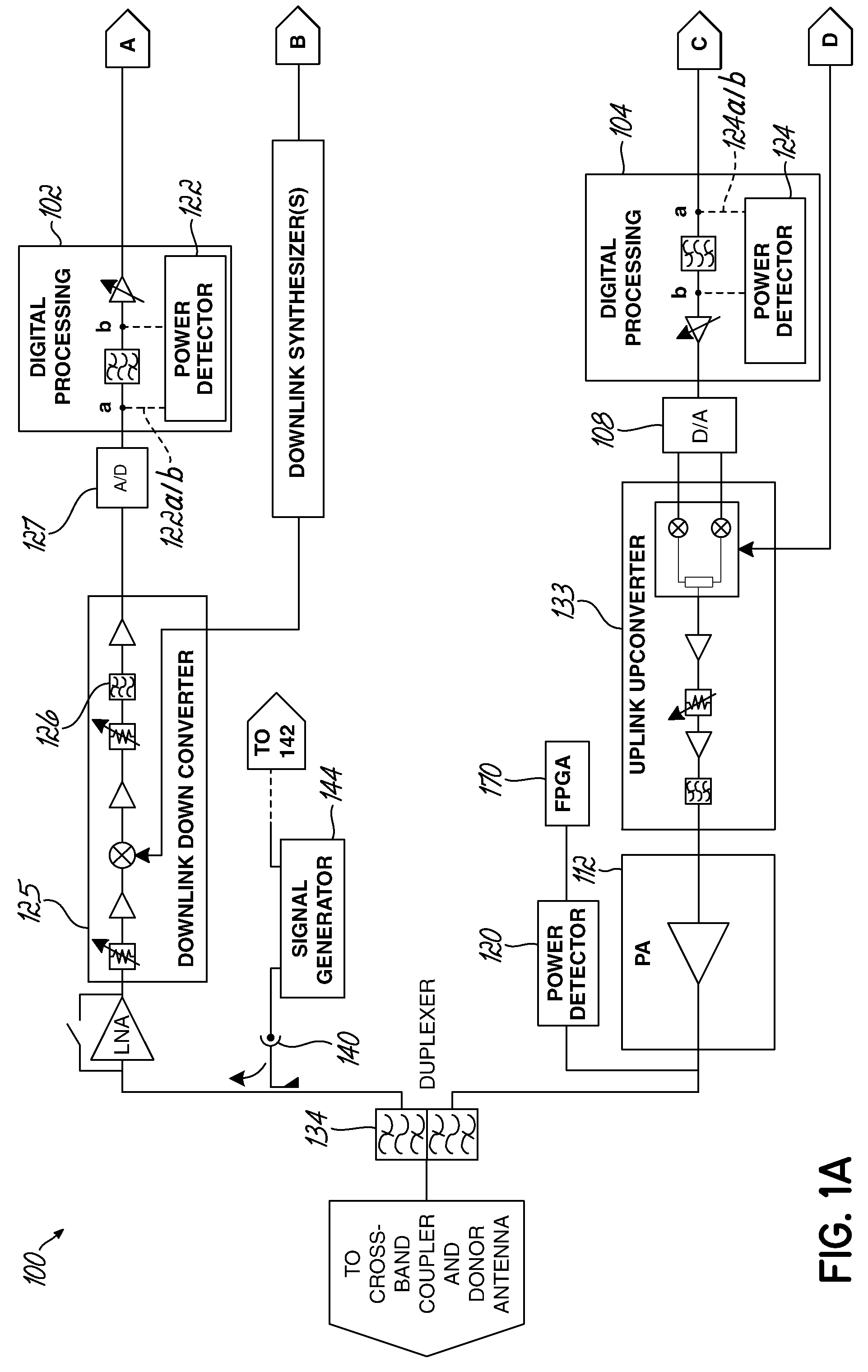
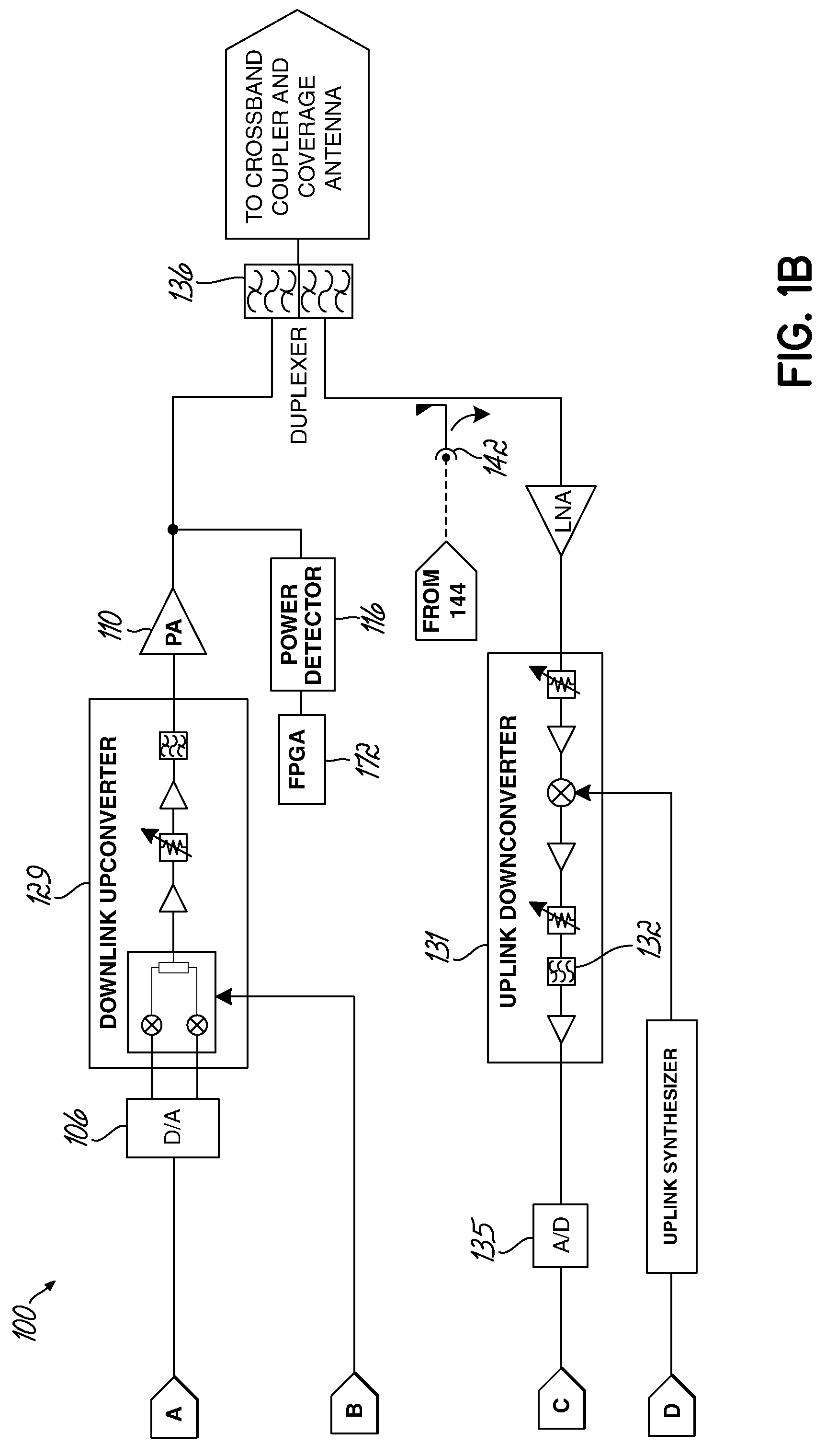
[0021]Embodiments of the present invention are directed to an apparatus and method of measuring or monitoring gain in a wireless communication system. Measurements of gain may be used for additional diagnostics, such as fault detection. For example, service providers are interested in knowing whether an amplifier in the communication system has blown or whether another component has failed, such that the communication system is not operating properly, in order to quickly service or replace the repeater or component. Some contemporary communication systems use power detectors to monitor or measure output power; however, such solutions cannot measure total system gain or identify fault conditions in a repeater because the input signal level is not known. A second detector could be placed at the repeater input, but this solution would be expensive due to the additional hardware and high dynamic range required. Instead, the various embodiments of the present invention offer lower cost s...


PUM


Abstract

A method of monitoring an element in wireless communication system is provided. An operational noise measurement is obtained by measuring a noise value outside of a bandwidth of a first device, but within a bandwidth of a second, subsequent device. The operational noise measurement is alternatively obtained by tuning an input band of the element to shift the input band partially or completely outside of a bandwidth of a first device to create an open band or by suppressing an input of the antenna and measuring noise within the open bandwidth of the element of the wireless communication network. A stored parameter is retrieved and compared to the measured operational noise. Alternatively, a leakage signal of the element may be received at a signal receiver and compared to a reference. The reference is a function of components of the wireless communication system in a leakage path of the leakage signal.

Description

FIELD OF THE INVENTION[0001]The present invention is directed to wireless transceiver systems for use in wireless communication systems, and specifically is directed to gain monitoring in the wireless transceiver systems.BACKGROUND OF THE INVENTION[0002]Contemporary cellular phone systems and broadband wireless metropolitan networks are generally divided into a number of cells distributed in a pattern to preclude co-channel interferences and provide coverage of mobile and fixed subscriber units operating within the service area of the system. Each cell generally includes a base station that employs radio frequency (RF) transceiver equipment, antennas, and wire line communication equipment. In addition, some cells also include repeaters, distributed antenna systems (DAS), and / or remote radio heads in order to extend the coverage of the base station over longer distances, throughout buildings or tunnels, around obstacles, etc. These coverage extension elements, hereafter generically r...

Claims


Application Information

Patent Timeline
Patent Type & Authority Applications(United States)
IPC IPC(8): H04B17/02H04B1/38H04B17/40
CPCH04B7/15535H04B17/02H04B17/40H04B17/23H04B17/345H04B17/21
Inventor HOBBS, NEIL T.SCHMIDT, JR., NELSON C.KUMMETZ, THOMASPHILLIPS, FRED
Owner COMMSCOPE TECH LLC
Why Eureka
Try Eureka