Miniature locator device for use with hunting arrows

a miniature locator and arrow technology, applied in the field of hunting arrows, can solve the problems of significant loss of game resulting from successful shots, high cost of arrows, and substantial financial loss and frustration

Active Publication Date: 2011-08-18
PRO TRACKER IP HLDG
View PDF95 Cites 10 Cited by
  • Summary
  • Abstract
  • Description
  • Claims
  • Application Information

AI Technical Summary

Benefits of technology

[0015]A further embodiment of the present disclosure may comprise a hunting arrow including an arrow shaft with a threaded distal end and a chamber access window in the shaft. The embodiment also has a chamber attachment that is inserted into or threaded onto the end of the shaft. The chamber attachment has an access window leading to a chamber. The hunting arrow also includes a transmitter housing having a signal generating transmitter housed therein. The transmitter housing has an animal engagement member, such as at least one barbed hook, extending therefrom. The transmitter housing may be installed into the chamber in the chamber attachment. A pair of shear pins may secure the transmitter housing in the chamber.
[0016]In yet a further embodiment of the present disclosure, a method of tracking a target animal is disclosed whereby a hunting arrow

Problems solved by technology

Such arrows are quite expensive, typically ranging in price from $10.00 to $50.00 apiece.
Two distinct problems are common with bow hunters: (1) locating the arrow resulting from a missed shot and (2) locating the injured animal (if an immediate kill is not made) resulting from a successful shot.
A typical hunter may lose 10-20 arrows per year, resulting in substantial financial loss and frustration.
Even more importantly, however, the loss of game resulting from successful shots is significant.
This results in the loss of many wounded animals, which is a great disappointment to the hunter, as well as a waste of natural resources.
However, while these arrows have addressed the problem of errant shots and successful shots, where the arrow remains imbedded in the quarry, in a significant number of cases of

Method used


Image

  • Miniature locator device for use with hunting arrows
  • Miniature locator device for use with hunting arrows
  • Miniature locator device for use with hunting arrows

Examples


Embodiment Construction

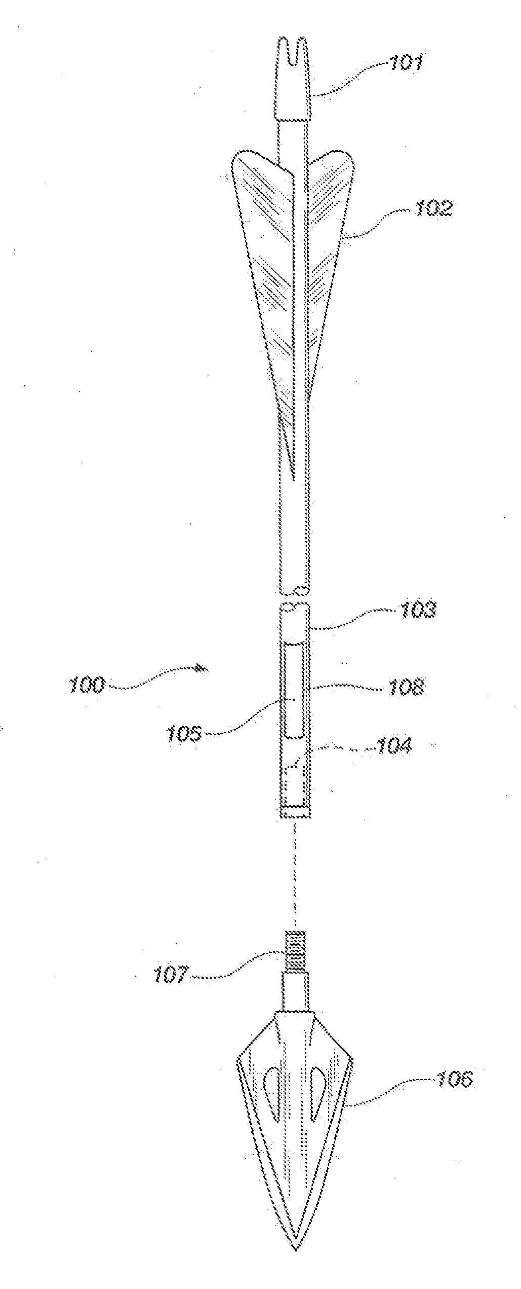
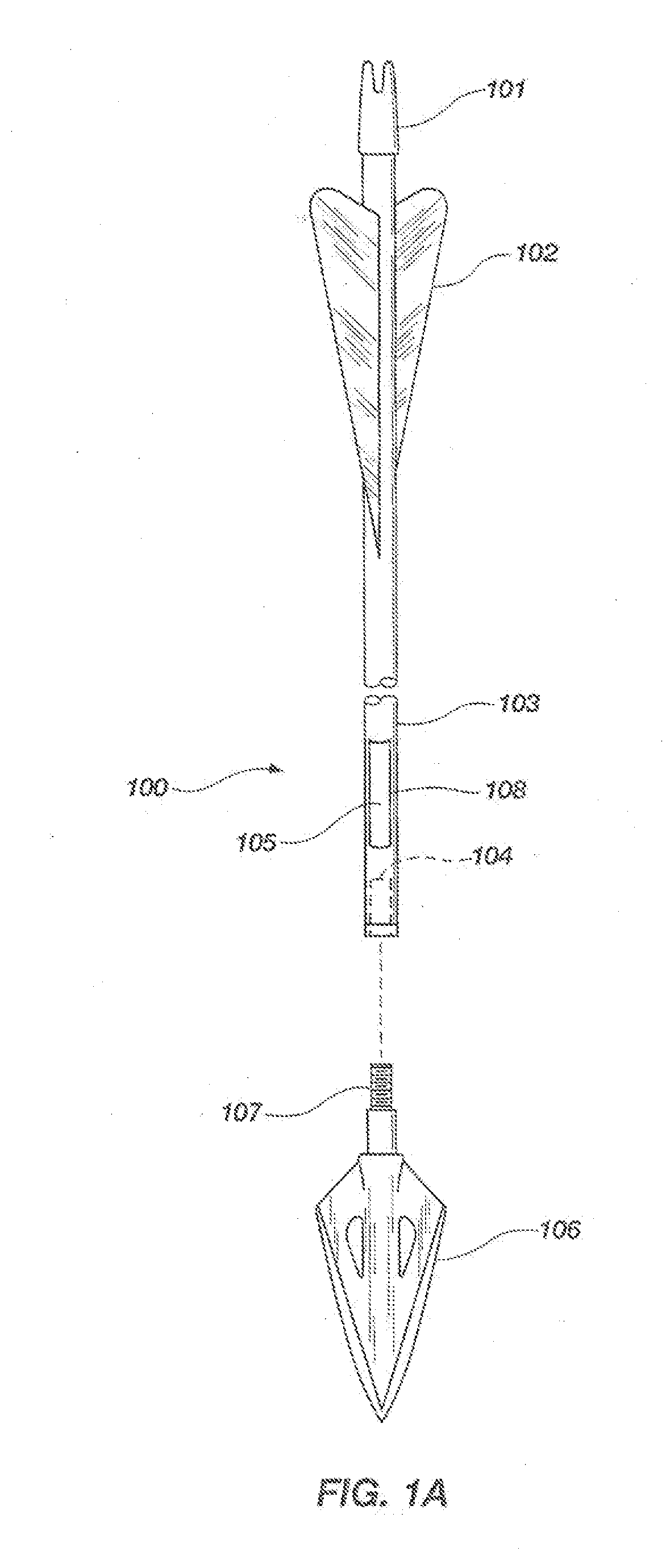
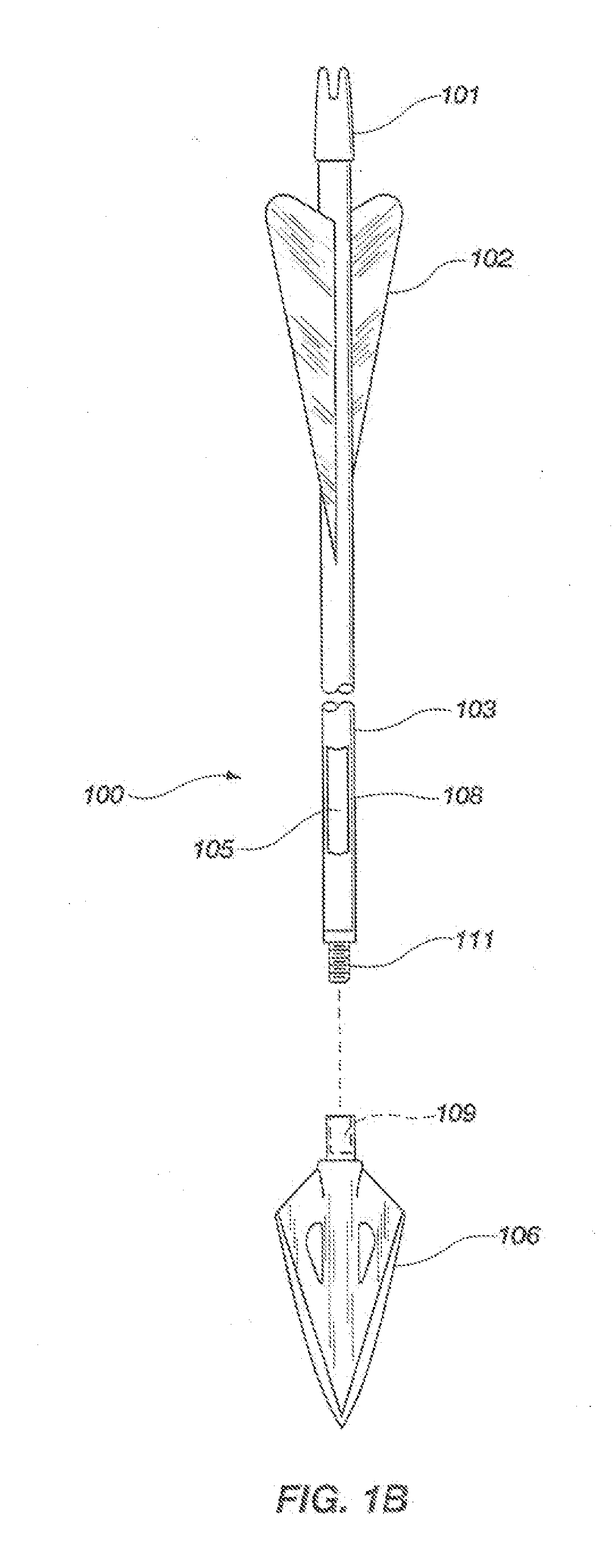
[0064]For the purposes of promoting an understanding of the principles in accordance with this disclosure, reference will now be made to the embodiments illustrated in the drawings and specific language will be used to describe the same. It will nevertheless be understood that no limitation of the scope of the disclosure is thereby intended. Any alterations and further modifications of the inventive features illustrated herein, and any additional applications of the principles of the disclosure as illustrated herein, which would normally occur to one skilled in the relevant art and having possession of this disclosure, are to be considered within the scope of the disclosure claimed.

[0065]Before the devices, systems, processes and methods for providing an implantable locator for tracking hunting animals are disclosed and described, it is to be understood that this disclosure is not limited to the particular configurations, process steps, and materials disclosed herein as such configu...


PUM


Abstract

A hunting arrow for tracking target animals is disclosed and described. The arrow can include a chamber. The arrow may also include a transmitter housing that is installable into the chamber. A pair of bores extending through the transmitter housing and chamber may be configured and adapted for receiving a pair of shear pins. The shear pins may secure the housing in the chamber. The transmitter housing may comprise an animal engagement member, such as a hook. The transmitter housing is ejected from the chamber when the arrow strikes a target animal and the hook stops the forward momentum of the transmitter housing with sufficient force to shear the shear pins, thereby ejecting and embedding the transmitter housing in the hide of the animal. The transmitter within the housing may broadcast the location of the animal to the hunter to enable easy tracking of the animal, if wounded.

Description

CROSS-REFERENCE TO RELATED APPLICATIONS[0001]This application is a continuation-in-part of U.S. patent application Ser. No. 12 / 884,145, filed on Sep. 16, 2010, which claims the benefit of U.S. Provisional Patent Application Ser. No. 61 / 296,207, filed Jan. 19, 2010, and U.S. Provisional Patent Application Ser. No. 61 / 243,049, filed Sep. 16, 2009, which are all hereby incorporated by reference herein in their entireties, including but not limited to those portions that specifically appear hereinafter, the incorporation by reference being made with the following exception: In the event that any portion of the above-referenced application is inconsistent with this application, this application supercedes the above-referenced application.STATEMENT REGARDING FEDERALLY SPONSORED RESEARCH AND DEVELOPMENT[0002]Not Applicable.BACKGROUND[0003]This disclosure relates generally to hunting arrows, and more particularly, but not necessarily entirely, to a hunting arrow having a transmitter, locate...

Claims


Application Information

Patent Timeline
IPC IPC(8): F42B6/04A01M31/00
CPCF42B12/385F41B5/1438F42B12/362F42B6/04F42B12/40
Inventor FERGUSON, MICHAEL D.
Owner PRO TRACKER IP HLDG
Why Eureka
Try Eureka