Socket liner for artificial limb

a technology of artificial limbs and socks, applied in the field of prosthetic devices, can solve the problems of large shear force on the stump, large amount of nerve bundle pressure or restriction, dramatic atrophy and tissue loss, etc., and achieve the effect of reducing air leakag

Inactive Publication Date: 2011-08-18
OTTO BOCK HEALTHCARE IP GMBH & CO KG
View PDF100 Cites 29 Cited by
  • Summary
  • Abstract
  • Description
  • Claims
  • Application Information

AI Technical Summary

Benefits of technology

[0026]A liner for a socket of an artificial limb, the socket configured to receive a portion of an amputee's residual limb and the liner, the liner including a liner interface for bonding th

Problems solved by technology

These types of sockets caused a lot of shear force on the stump 14 as well as had pressure or restriction problems on the nerve bundles and vascular flow of fluid by way of the circumferential pressure effect of the socket on the limb.
However, the problematic tissue configurations, such as bony prominences, required special consideration such as the addition of soft or pliable materials to be put into the socket.
The problem with this is that it is a very specific pressure and creates atrophy and loss of tissue dramatically over these high pressure areas.
None of these systems employs positive pressure distributed over the total contact area between the residual limb and the artificial limb socket to accommodate volume changes within the socket.
However, there are no systems that employ a negative pressure produced by a vacuum pump to lock the residual limb to the artificial limb.
This did not work particularly well because it would cause swelling of the residual limb into the chamber created by the negative dr

Method used


Image

  • Socket liner for artificial limb
  • Socket liner for artificial limb
  • Socket liner for artificial limb

Examples


first embodiment

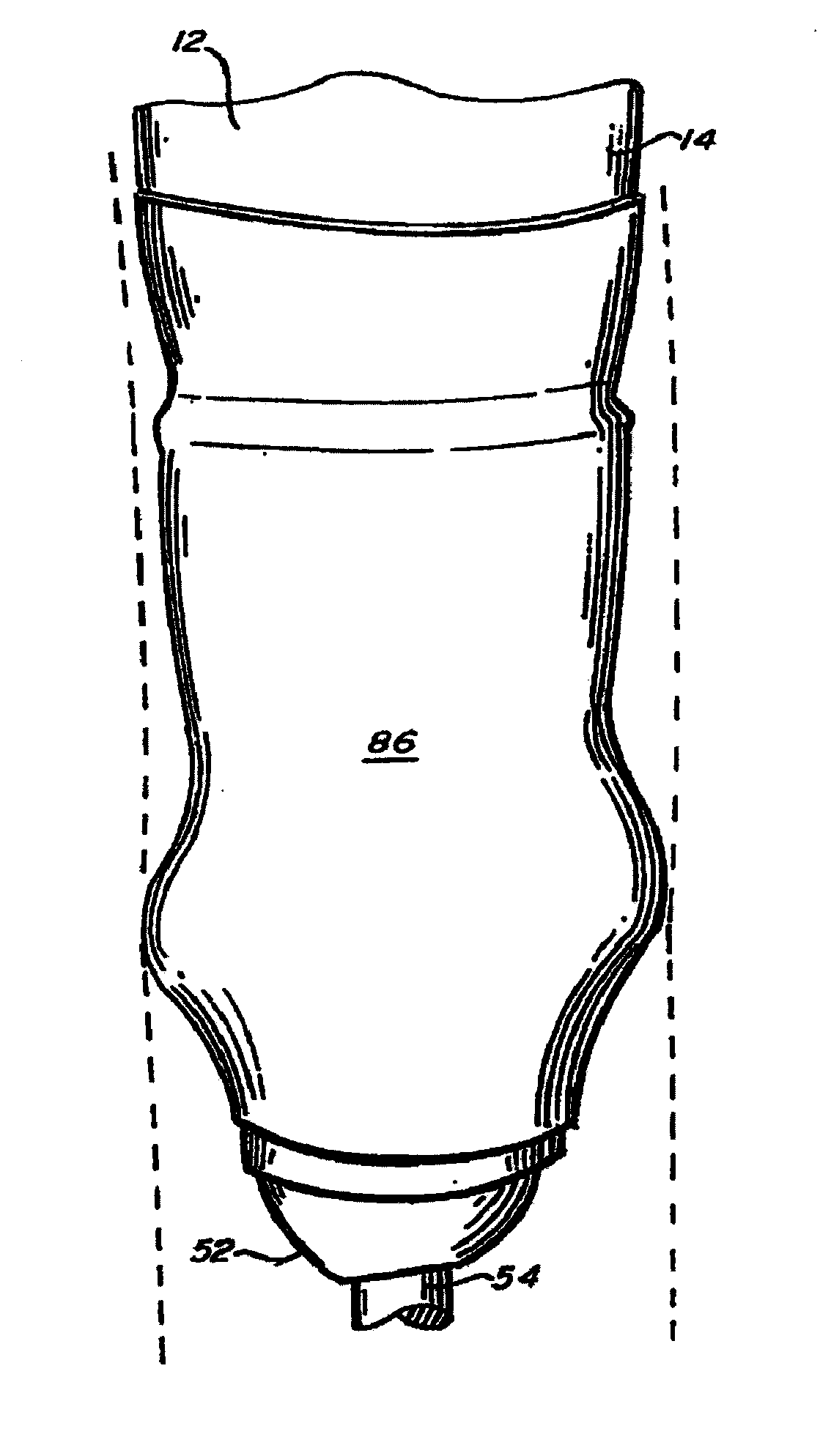
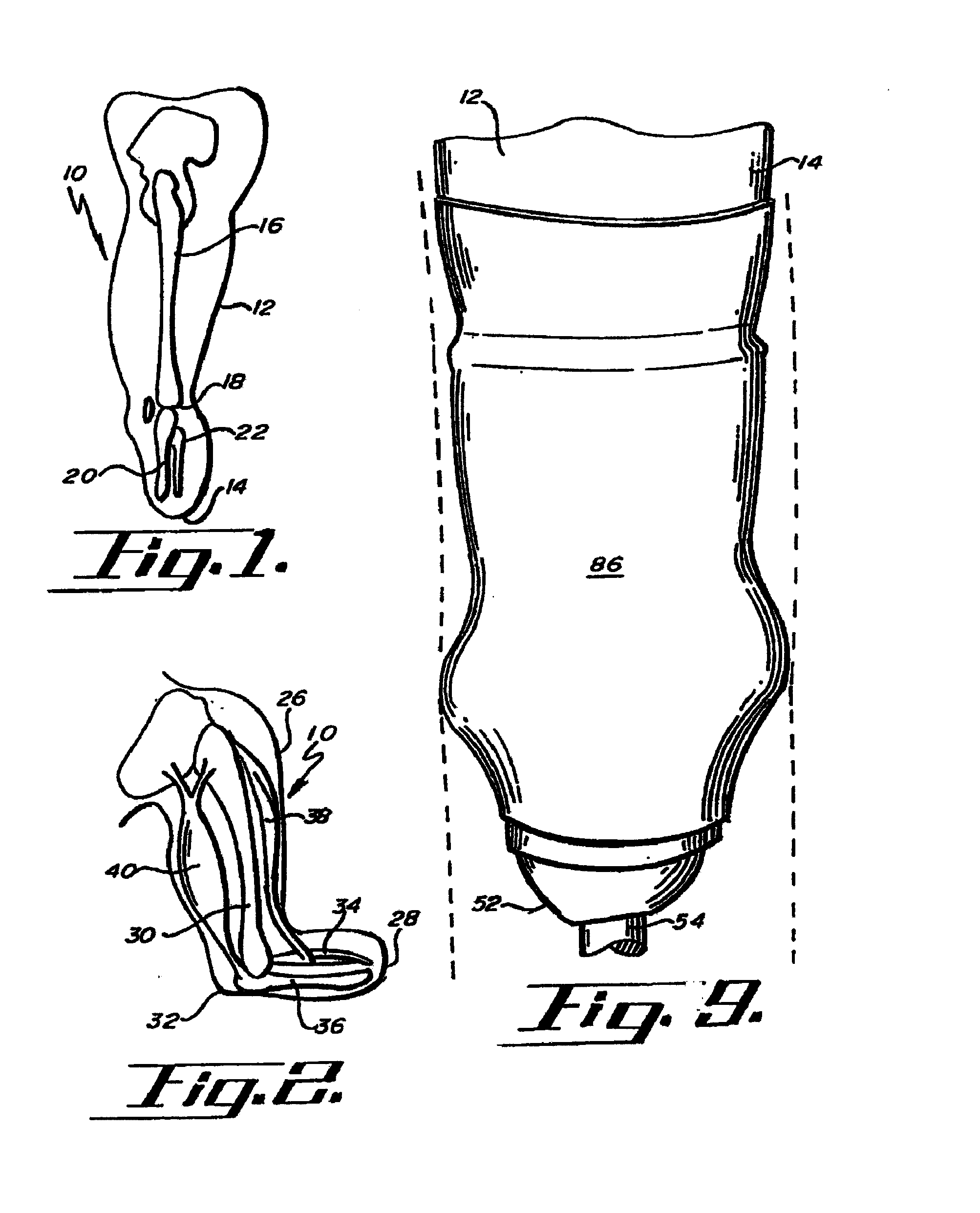
[0051]the hypobarically-controlled artificial limb 50 is shown in FIG. 4. The hypobarically-controlled artificial limb 50 further includes a flexible inner socket 60 with a cavity 62 with a volume and shape for receiving a substantial portion of the residual limb 14 and fitting in the space 58 between the outer socket 52 and the residual limb 14. The inner socket 60 has an inner surface 64 opposing the residual limb 14 and an outer surface 66 opposing the outer socket 52.

[0052]A vacuum source 70 may conveniently be attached to the shin or pylori 54. The vacuum source 70 may preferably be a mechanical or motor-driven pump 72. The vacuum source 70 is connected to a power source 83, which may be a battery.

[0053]A vacuum valve 74 is suitably connected to the vacuum source 70. The vacuum valve 74 may preferably be disposed on the outer socket 52. A vacuum tube 76 connects the vacuum valve 74 to the cavity 62. It will be seen that the vacuum source will cause the residual limb 14 to be dr...

third embodiment

[0071]The vacuum source 70, under control of the regulator means 80, will compensate for reduced residual limb volume up to a certain point. From that point on, the regulator means 80 will cause the positive air pressure source 100 to further compensate for reduced residual limb volume as described above. The third embodiment thus uses both vacuum and positive air pressure working together to lock the residual limb 14 into the inner socket 60 and reduce socket volume to compensate for fluid loss in the residual limb 14. The exact point at which the changeover is made between vacuum compensation and positive air pressure compensation is controlled by the regulator means 80, which as described may be a digital computer appropriately programmed for the socket environment.

[0072]A fourth embodiment of the hypobarically-controlled artificial limb 50 is shown in FIG. 8. The fourth embodiment is like the first embodiment, but includes two vacuum valves: a first vacuum valve 106 and a second...

fourth embodiment

[0076]The fourth embodiment may also include a positive air pressure source 100 as previously described, to adjust the size of the inner socket 60B to compensate for decreased residual limb volume.

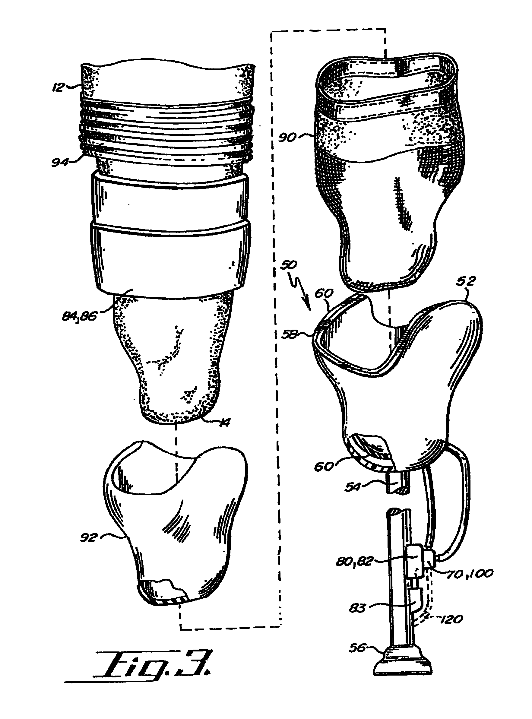
[0077]The fourth embodiment may also include a thin sheath 90, liner 92, and second sleeve 94, as previously described (see FIG. 3).

[0078]The positive air pressure source 100 may also be used for shock absorption and a dynamic response in the ankle and foot sections of the artificial limb 50, by means of a connection 120.

[0079]A fifth embodiment of the hypobarically-controlled artificial limb 50 is shown in FIG. 10. This embodiment is the same as the first embodiment shown in FIG. 4, with some changes. First, vacuum source 71 may be a hand-operated vacuum pump 71 which may remove air from the cavity 62 down to approximately 15-25 inches of mercury. A suitable hand-operated vacuum pump is marketed under the trademark MITY VAC II® by Neward Enterprises, Inc. of Cucamonga, Calif.


PUM


Abstract

A hypobarically-controlled artificial limb for amputees includes a single socket with a volume and shape to receive a substantial portion of the residual limb. A sealed cavity is formed between the socket and the residual limb. The wearer may use a liner over the residual limb for comfort. A vacuum source is connected to a vacuum valve connected to the cavity to suspend the artificial limb from the residual limb and to control and minimize volumetric and fluid changes within the residual limb A liner for a hypobarically-controlled socket for an artificial limb, with a liner interface bonding the liner to the socket and forming a seal between the liner and the socket. The liner may be permanently attached to the socket or the liner may be removed from the socket for replacement.

Description

RELATED APPLICATIONS[0001]This is a divisional of U.S. patent application Ser. No. 10 / 740,938, filed on 17 Dec. 2003, now pending, which is a continuation of U.S. patent application Ser. No. 09 / 670,853, filed on 27 Sep. 2000, now abandoned, which is a continuation-hi-part of U.S. patent application Ser. No. 09 / 492,406, filed on 27 Jan. 2000, now U.S. Pat. No. 6,508,842 B1, issued 21 Jan. 2003, which is a continuation-in-part of U.S. patent application Ser. No. 09 / 325,297, filed on 3 Jun. 1999, now abandoned.BACKGROUND OF THE INVENTION[0002]The present invention relates to prosthetic devices and more particularly to a hypobarically-controlled artificial limb for amputees.[0003]An amputee is a person who has lost part of an extremity or limb such as a leg or arm that commonly may be termed as a residual limb. Residual limbs come in various sizes and shapes with respect to the stump. That is, most new amputations are either slightly bulbous or cylindrical in shape while older amputatio...

Claims


Application Information

Patent Timeline
IPC IPC(8): A61F2/80A61F2/00A61F2/50A61F2/60A61F2/66A61F2/70A61F2/74A61F2/76A61F2/78
CPCA61F2/5046A61F2210/009A61F2/7812A61F2/7843A61F2/80A61F2002/5003A61F2002/5015A61F2002/5052A61F2002/5053A61F2002/6614A61F2002/704A61F2002/747A61F2002/7655A61F2002/7806A61F2002/7818A61F2002/7881A61F2002/802A61F2002/805A61F2210/0057A61F2/601A61F2/74
Inventor CASPERS, CARL A.
Owner OTTO BOCK HEALTHCARE IP GMBH & CO KG
Why Eureka
Try Eureka