Air vent apparatus for vehicle

a technology for air vents and vehicles, which is applied to vehicle components, vehicle heating/cooling devices, transportation and packaging, etc., can solve the problems of increasing cost, increasing manufacturing costs, and increasing parts, and achieving the effects of reducing cost, reducing weight, and reducing parts

Inactive Publication Date: 2015-07-02
HYUNDAI MOTOR CO LTD +1
View PDF4 Cites 5 Cited by
  • Summary
  • Abstract
  • Description
  • Claims
  • Application Information

AI Technical Summary

Benefits of technology

[0012]Various aspects of the present invention are directed to providing an air vent apparatus for a vehicle, in which a plurality of outer wings is integrally formed using a wing nozzle connecting edges of the outer wings to each other, and the integrated outer wings and a plurality of inner wings are coupled to a spacer defining one space, and the spacer is installed at a duct, thus eliminating the use of the wing link for connecting the outer wings to each other, therefore achieving a reduction in the number of parts, a reduction in cost, and a reduction in weight, in addition to reducing a mold cost and enhancing the degree of freedom in design.
[0014]The air vent apparatus may further include a duct cover coupled to a front edge of the duct to cover a front edge of the spacer and minimizing leakage of air through a gap between the duct and the spacer.
[0017]The wing nozzle is airtightly coupled to the spacer to minimize leakage of air between the wing nozzle and the spacer.
[0022]A sealing member is coupled to the cylindrical seat of the duct to reduce a gap between the duct and the spacer and thereby minimize the leakage of air.
[0023]The sealing member is made of non-woven fabric to reduce the gap between the duct and the spacer while allowing for rotation of the spacer.
[0024]As is apparent from the above description, the air vent apparatus for the vehicle is advantageous in that the plurality of outer wings is integrated with the wing nozzle using the circular ring shaped wing nozzle, thus eliminating the use of the wing link for connecting the outer wings, therefore achieving a reduction in the number of parts, a reduction in cost, and a reduction in weight, and in that the wing link for the outer wings having a complicated assembling structure is not used, thus reducing a mold cost and enhancing the degree of freedom in design.

Problems solved by technology

However, the conventional air vent 2 is problematic in that the plurality of outer wings 2c are connected to each other via a wing link (not shown) in such a way as to be integrally moved, so that the number of parts, manufacturing cost, and weight are inevitably increased due to the use of the wing link.
Such a configuration makes a mold complicated, thus leading to an increase in cost, and requires an excessively long assembly time, thus leading to a reduction in productivity.
Furthermore, the conventional air vent 2 is problematic in that an additional space should be required to operate the wing link connecting the outer wings 2c to each other, so that a degree of freedom in designing the air vent 2 is low.

Method used


Image

  • Air vent apparatus for vehicle
  • Air vent apparatus for vehicle
  • Air vent apparatus for vehicle

Examples


Embodiment Construction

[0034]Hereinbelow, an air vent apparatus for a vehicle according to the preferred embodiment of the present invention will be described with reference to the accompanying drawings.

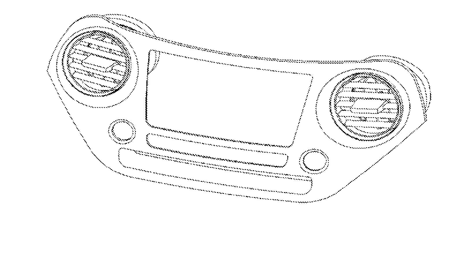
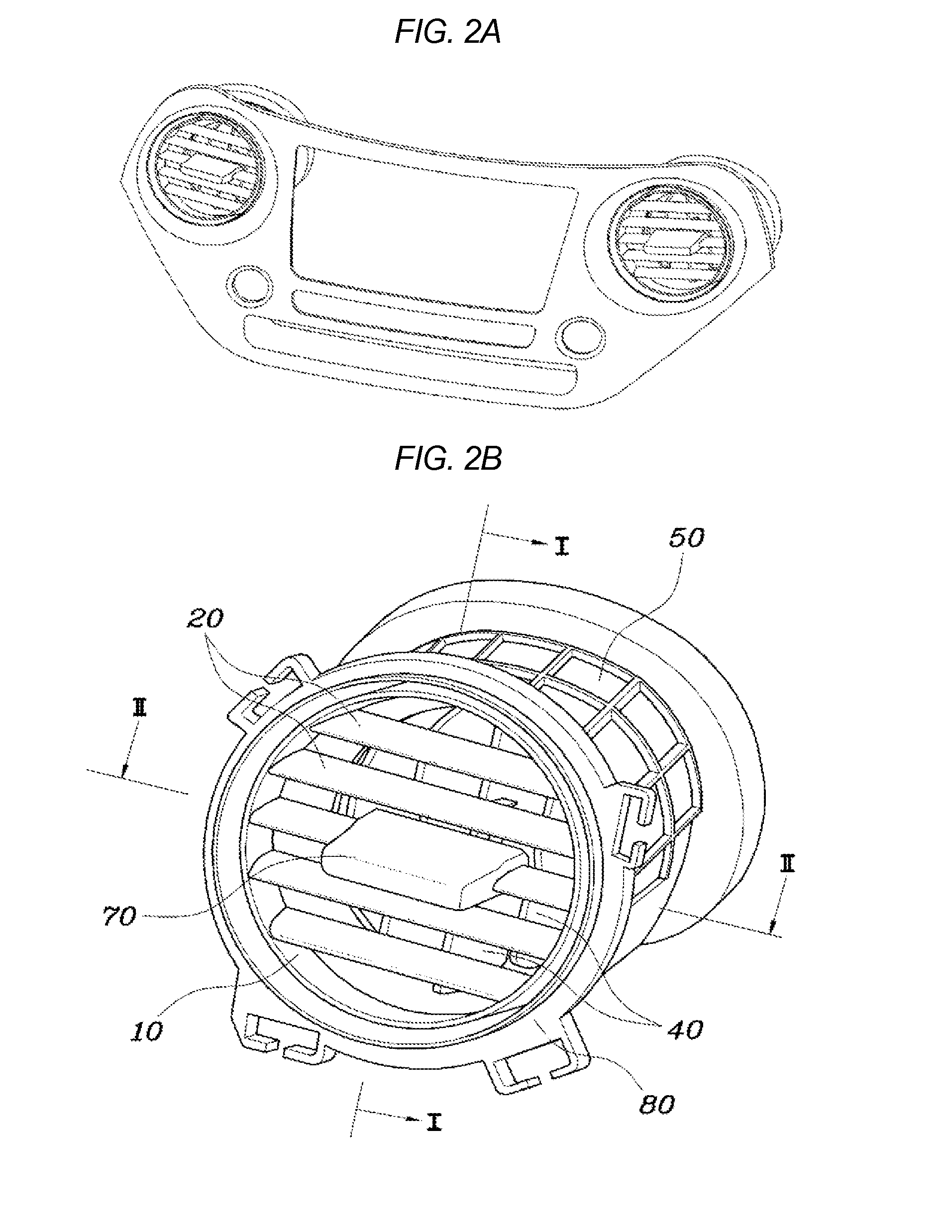
[0035]As shown in FIGS. 2A and 2B through FIGS. 9A to 9C, the air vent apparatus for the vehicle according to the present invention includes outer wings 20, a plurality of inner wings 40, a spacer 60, and a knob 70. The outer wings 20 are integrated with a wing nozzle 10. The inner wings 40 are connected to each other via a wing link 30. The wing nozzle 10 is fixedly coupled to the spacer 60, and the inner wings 40 are rotatably coupled to the spacer 60. The spacer 60 is rotatably coupled to the duct 50. The knob 70 is coupled to the inner wings 40 while being fitted to the outer wings 20, thus rotating the inner wings 40 relative to the spacer 60.

[0036]The air vent apparatus for the vehicle according to the present invention further includes a duct cover 80 which is coupled to a front edge of the duct 50 ...


PUM


Abstract

An air vent apparatus for a vehicle may include an outer wing integrated with a wing nozzle, a plurality of inner wings coupled to each other via a wing link, a spacer to which the wing nozzle may be fixedly coupled, the inner wings being rotatably coupled to the spacer, the spacer being rotatably coupled to the duct, and a knob coupled to the inner wings while being fitted to the outer wing, thus rotating the inner wings relative to the spacer.

Description

[0001]The present application claims priority of Korean Patent Application Number 10-2013-0164906 filed on Dec. 27, 2013, the entire contents of which application are incorporated herein for all purposes by this reference.BACKGROUND OF THE INVENTION[0002]1. Field of the Invention[0003]The present invention relates to air vent apparatuses for vehicles, and, more particularly, to an air vent apparatus for a vehicle, which is configured so that a plurality of outer wings is integrated with each other by a wing nozzle.[0004]2. Description of Related Art[0005]FIGS. 1A and 1B show an example of an air vent 2 mounted to a vehicle dashboard 1. The air vent 2 functions to discharge cold or warm air, which is generated from an air-conditioning device, to an interior of a vehicle. The air vent 2 includes a duct 2a that guides an air flow to the interior of the vehicle, a plurality of inner wings 2b that are rotated to guide an air discharge direction leftwards and rightwards, a plurality of ou...

Claims


Application Information

Patent Timeline
Patent Type & Authority Applications(United States)
IPC IPC(8): B60H1/34B60H1/24
CPCB60H1/246B60H1/3414B60H1/3428
Inventor KWON, HYUK JAENOH, HONG KIL
Owner HYUNDAI MOTOR CO LTD
Why Eureka
Try Eureka