Cannula Security Piece

Inactive Publication Date: 2011-08-25
HASHEMIEH JULIA
View PDF13 Cites 12 Cited by
  • Summary
  • Abstract
  • Description
  • Claims
  • Application Information

AI Technical Summary

Benefits of technology

[0009]In view of the foregoing disadvantages inherent in the known types of nasal cannula systems now present in the prior art, the present invention provides a new nasal c

Problems solved by technology

However, it is common for this tension to be relaxed, causing sag along the length of the tube.
All too common, the cannula may become dislodged from the back of the patient's ears, pulling the prongs away from the nostrils and reducing their effectiveness to deliver air flow to the patient.
The friction generated between the tube and the patient's skin can produce painful skin irritation and sores.
The patient's discomfort is c

Method used


Image

  • Cannula Security Piece
  • Cannula Security Piece

Examples


Example

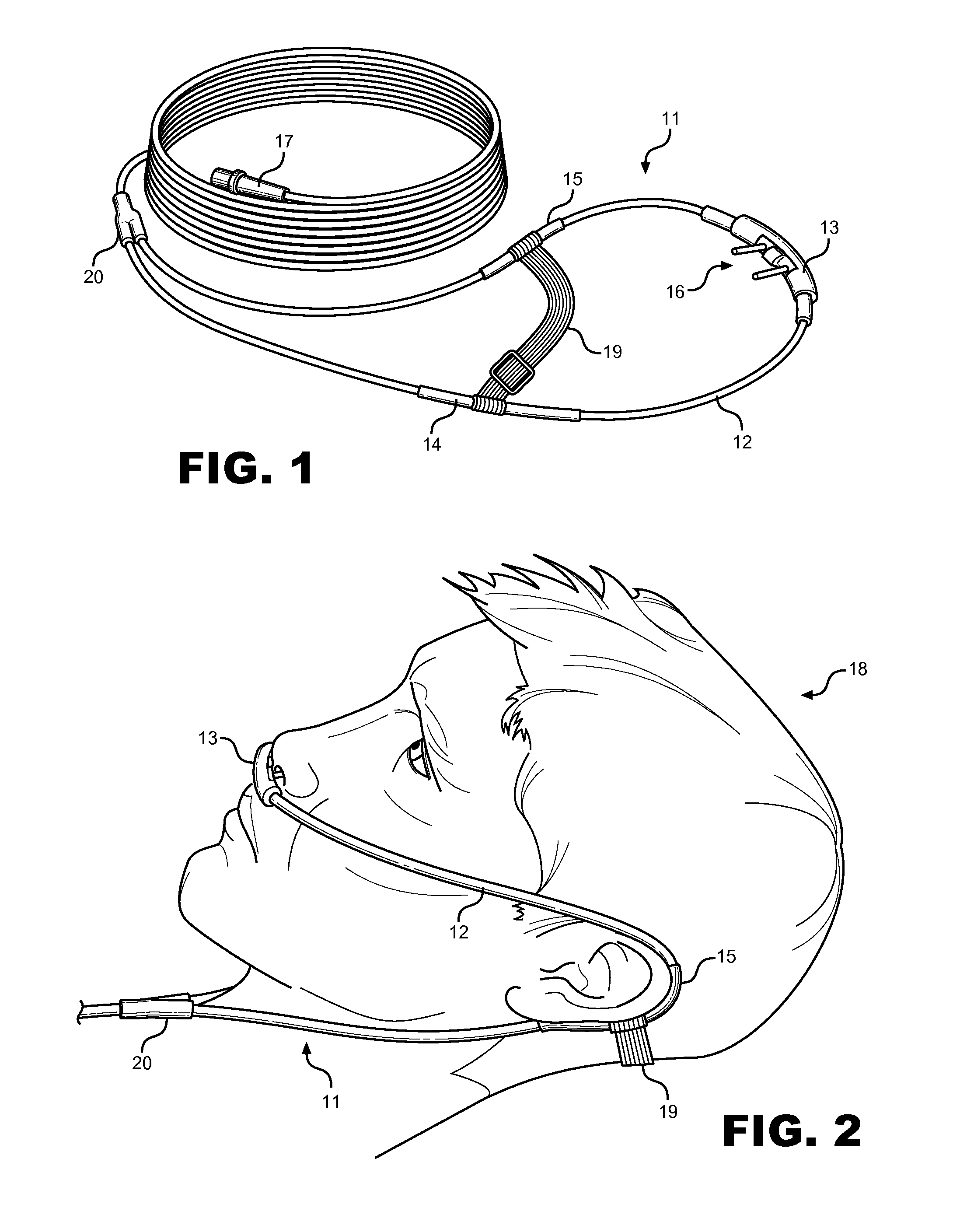
[0016]Referring now to FIG. 1, there is shown a perspective view of a nasal cannula 11 and the elements of the nasal cannula system. An annular nostril sleeve 13 covers a section of tubing 12 beneath a patient's nostrils. The nostril sleeve 13 provides openings to allow the cannula prongs 16 to protrude through. A set of annular ear sleeves 14,15 circumferentially attach to sections of tubing 12 near the patient's ears. A retaining strap 19 slideably attaches both ear sleeves 14,15 together. Finally, a neck sleeve 20 covers the junction of cannula tubing 12 along the patient's neckline.

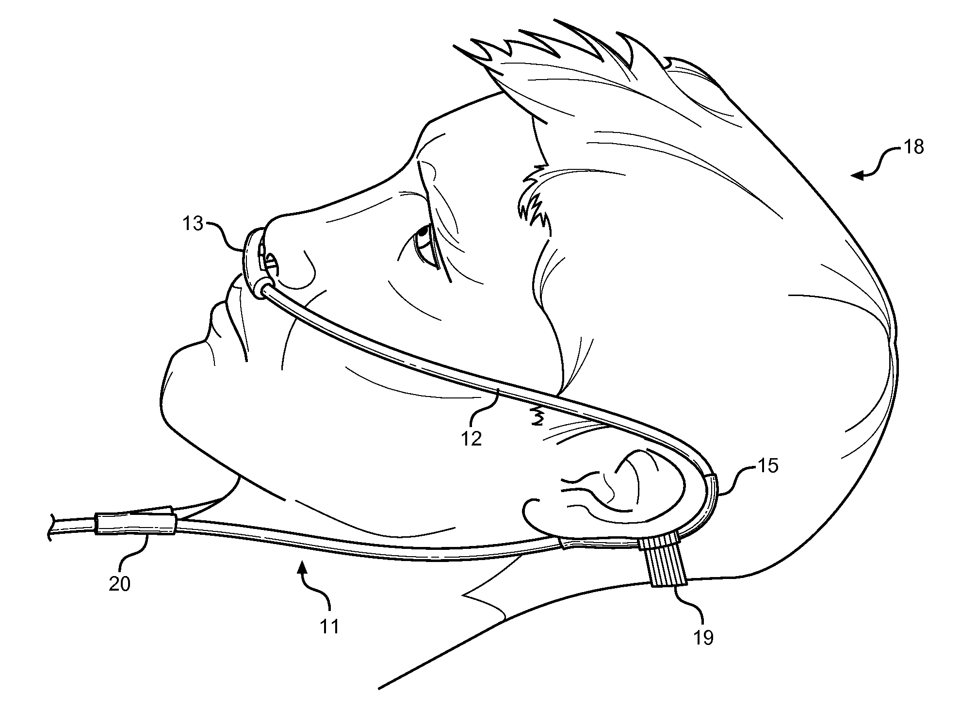
[0017]Referring now to FIG. 2, there is shown a side view of the nasal cannula system in its working position, attached to a patient's head 18. The nostril sleeve 13 sits at the base of the nose and prevents the tubing 12 around the prongs 16 from rubbing against the patient's skin. Ear sleeves 14, 15 surround the cannula tubing 12 behind the patient's ears, increasing the cross-section of the tubing ...


PUM


Abstract

A set of annular sleeves circumferentially mounted along sections of a nasal cannula. The sleeves are protective devices that prevent skin irritation and bed sores from developing after prolonged use of a nasal cannula. Improved stability of the cannula tube is also provided in the form of a sleeve connecting strap between ear sleeves, preventing dislocation of the cannula from the patient. The sleeves comprise tubular sections with an interior and an exterior surface. The interior surface contacts the outer diameter of the cannula breathing tube while the exterior surface contacts the patient under the nostrils, along the neck, and around the ears. The sleeves increase the cross-section of the cannula tube for improved fitment, while the strap reacts pull-off load.

Description

CROSS REFERENCE TO RELATED APPLICATION[0001]This application claims the benefit of U.S. Provisional Application No. 61 / 305,980 filed on Feb. 19, 2010, entitled “Cannula Security Piece”BACKGROUND OF THE INVENTION[0002]1. FIELD OF THE INVENTION[0003]The present invention relates to nasal cannulas, more specifically to annular sleeves attachable to a nasal cannula for prevention of skin irritation and dislocation.[0004]2. DESCRIPTION OF THE PRIOR ART[0005]A nasal cannula is a useful device that supplies supplemental air flow to medical patients. These patients may require assisted breathing or increased oxygen levels, including patients recovering from a surgery, elderly patients or those that are extendedly bedridden. The device comprises a hollow plastic tube that connects to an air flow generator, extends upward towards a patient and wraps around his or her ears, and finally connects into a patient's nostrils using a set of prongs that introduce the flow of air.[0006]A cannula is ty...

Claims


Application Information

Patent Timeline
IPC IPC(8): A61M16/00
CPCA61M16/0666A61M16/0672A61M16/0683A61M16/0833
Inventor HASHEMIEH, JULIA
Owner HASHEMIEH JULIA
Why Eureka
Try Eureka