
Composite Conductive Plastic Filler Panel

Active Publication Date: 2011-08-25
FUJITSU LTD
View PDF6 Cites 2 Cited by
  • Summary
  • Abstract
  • Description
  • Claims
  • Application Information

AI Technical Summary

Benefits of technology

[0005]The present disclosure provides a composite conductive filler panel that substantially eliminates or reduces at least some of the disadvantages and problems associated with previous methods and systems.
[0008]Technical advantages of certain embodiments of the present disclosure include providing an efficient means of manufacturing filler panels such that electromagnetic shielding requirements are met, while still providing the manufacturer or supplier flexibility in production costs and end-user customization. More particularly, this approach allows for a modular design and manufacture of filler panels in a way that reduces the manufacturing cost while maintaining performance. Further, the end-user is given greater options both in deciding the aesthetic look of a filler panel and in handling that panel after it is delivered. Other technical advantages will be readily apparent to one skilled in the art from the following figures, descriptions, and claims. Moreover, while specific advantages have been enumerated above, various embodiments may include all, some or none of the enumerated advantages.

Problems solved by technology

However, in many instances not all available space within the rack is in use at a given point in time.
Existing filler panels, while functional, tend to be expensive and difficult to customize for individual users or end-users.
As more electronics infrastructure is stored and operated in consolidated racks or shelves, manufacturers and suppliers of such racks face increasing challenges in maintaining performance levels required by end-users while reducing the manufacturing and operating costs.

Method used


Image

  • Composite Conductive Plastic Filler Panel
  • Composite Conductive Plastic Filler Panel
  • Composite Conductive Plastic Filler Panel

Examples


Embodiment Construction

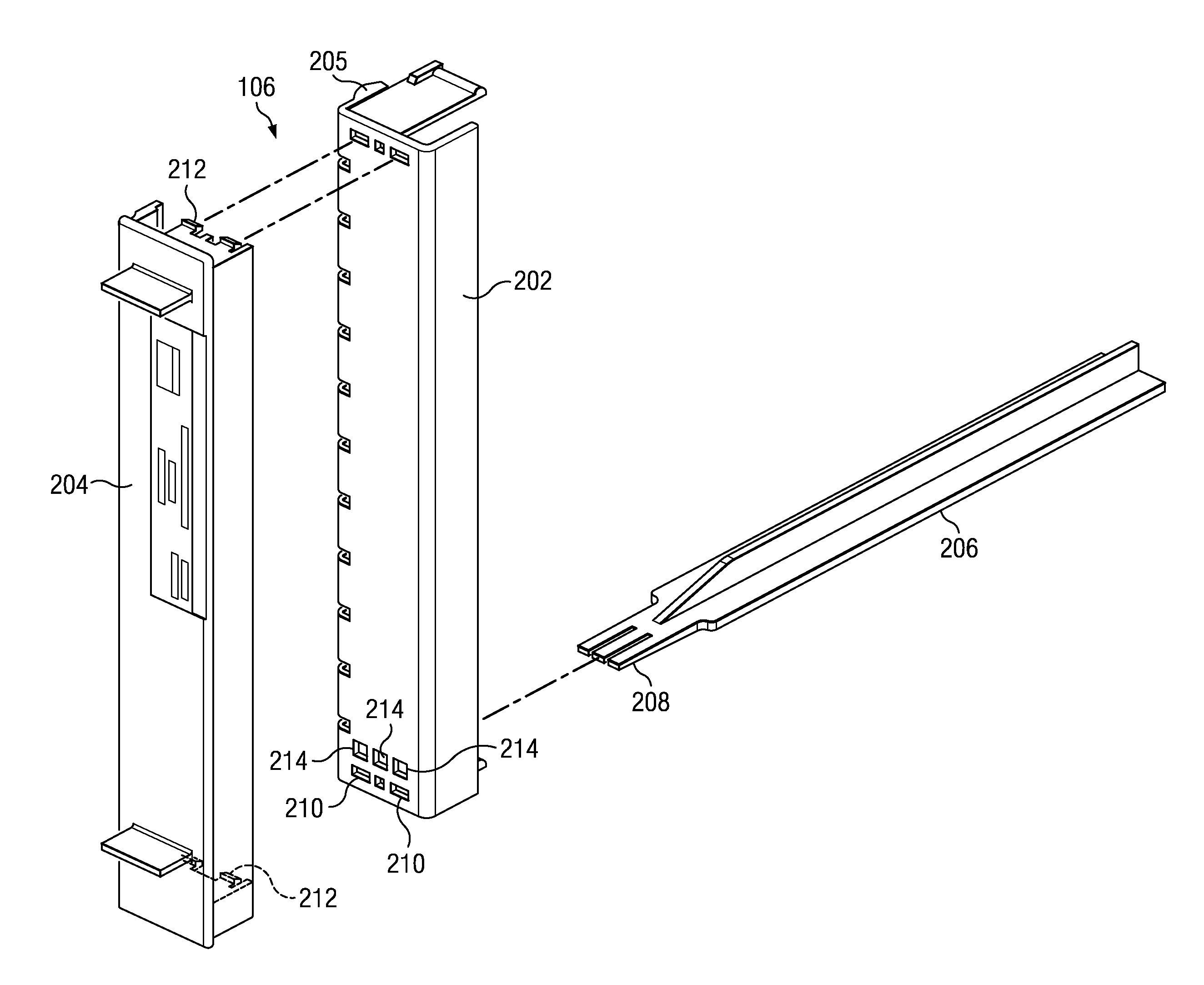
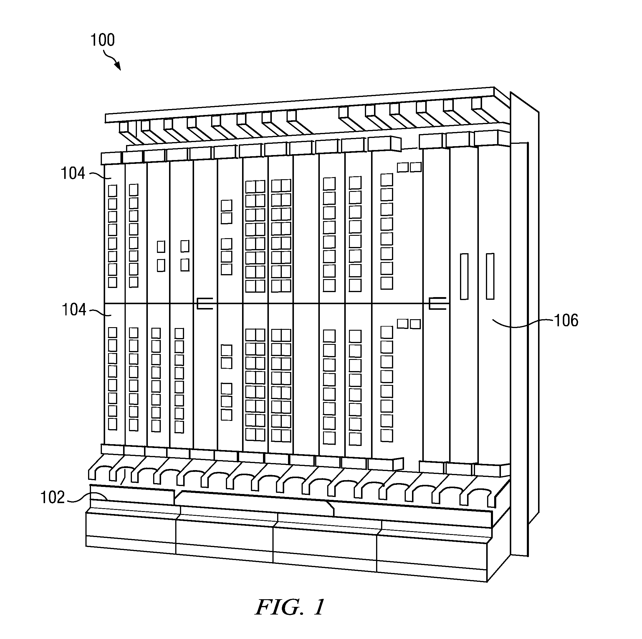
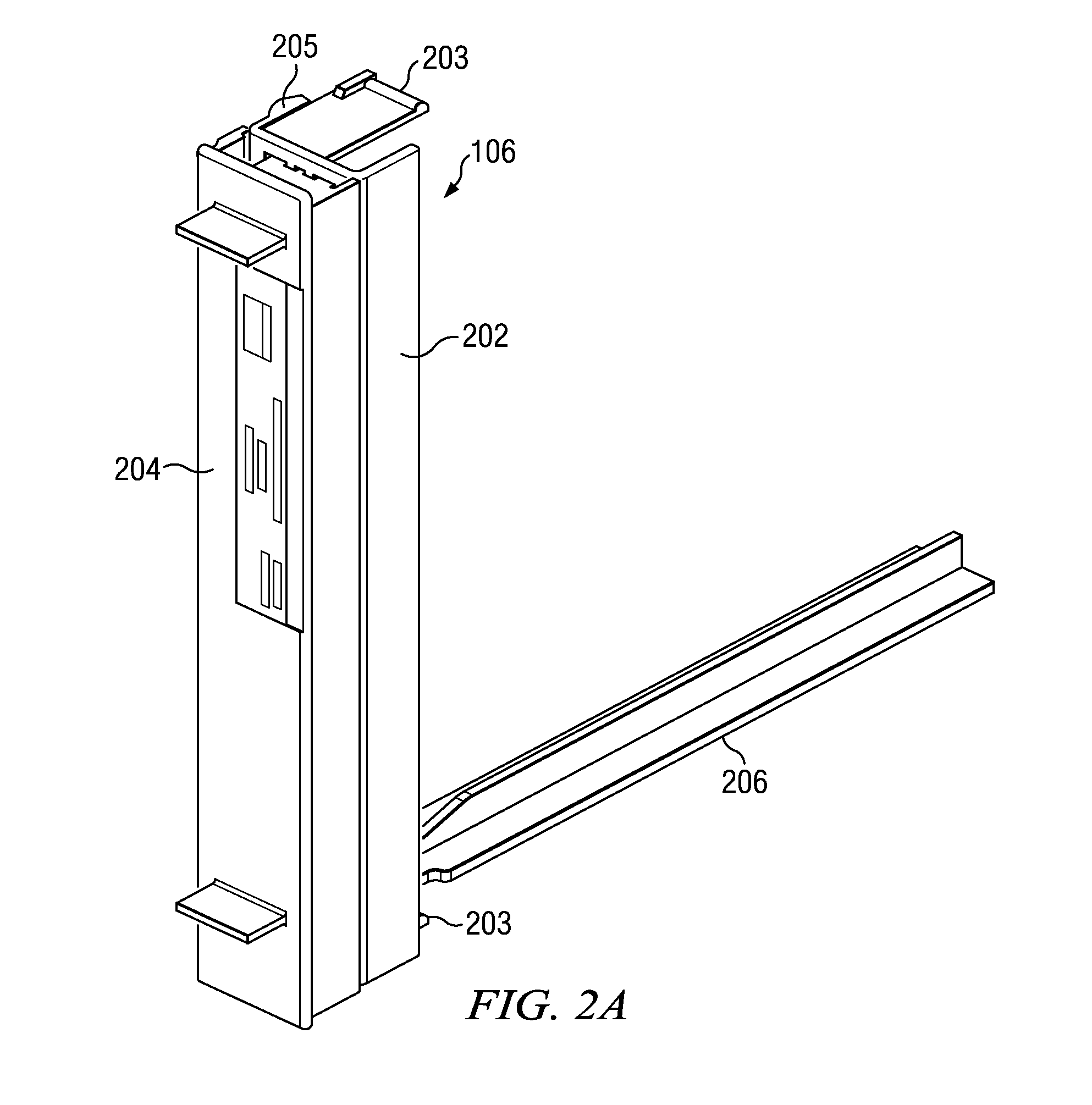
[0014]Preferred embodiments and their advantages are best understood by reference to FIGS. 1 through 3, wherein like numbers are used to indicate like and corresponding parts.

[0015]For the purposes of this disclosure, an electronic device may include any device or component configured for use in an electronics system, whether optical, mechanical, electrical, or otherwise. For example, an electronic device may be an optical amplifier card, a network storage device, a network interface card, multiplexor, or other device or component used in an electronics system and configured to be stored, maintained, and / or operated within a storage shelf or rack. Such a shelf or rack may be of standard size that accepts modular components, or may be custom-built and sized for a particular purpose. An electronic device may also include any electronic device or component configured for storage and / or operation in a rack or shelf system, such as a computer server that houses server blades or other cir...


PUM


Abstract

A filler panel for blocking an unused portion of a communications system. That filler panel may include an electromagnetic shielding base and a base cover removably coupled to the electromagnetic shielding base. The filler panel may also include an air dam composed substantially of low-cost, nonconductive material coupled to either the electromagnetic shielding base or to the base cover through the electromagnetic shielding base.

Description

TECHNICAL FIELD[0001]This disclosure relates in general to electronic card shelf systems and more particularly to a composite conductive plastic filler panel.BACKGROUND[0002]The infrastructure behind modern electronic systems increasingly requires deployment of multiple communication devices in systems that consolidate the various device components into racks or shelves, which may reduce the storage and operation space required by the owner of the infrastructure as well as easing the effort required for operation or maintenance. The devices stored in these racks or shelves may include communication network components such as amplifiers, switches, network management cards, network interface cards, or other devices. However, in many instances not all available space within the rack is in use at a given point in time.[0003]Filler panels are devices used to fill the unused space in such a rack or shelf. These panels serve many uses, including electromagnetic shielding (to ensure proper ...

Claims


Application Information

Patent Timeline
IPC IPC(8): H05K9/00
CPCH05K9/0018
Inventor PEDOEEM, ALBERTMISTRY, MAHESH
Owner FUJITSU LTD
Learn More