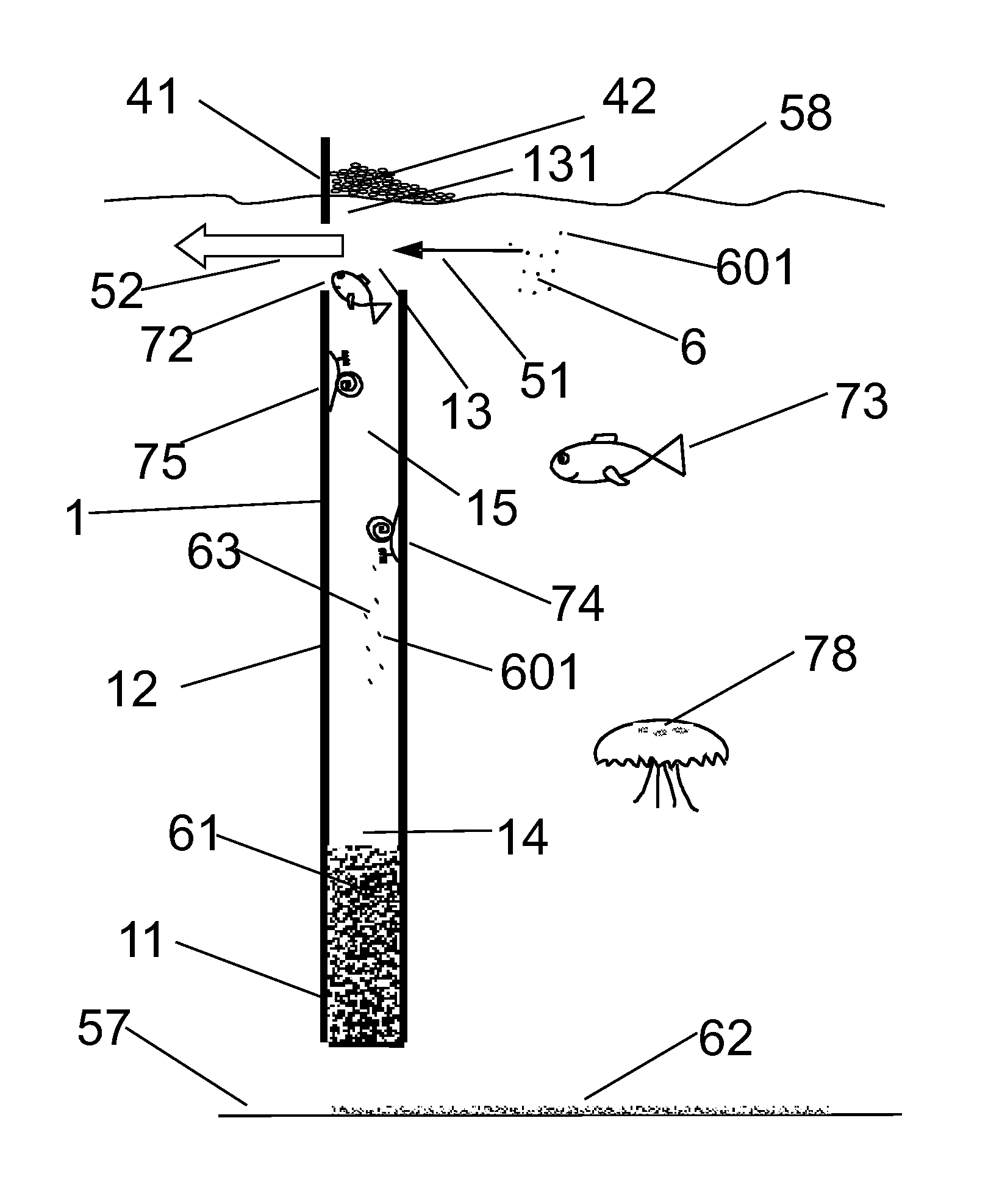
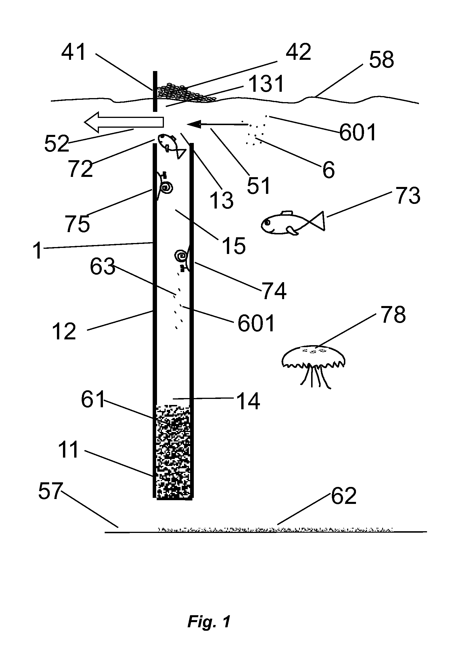
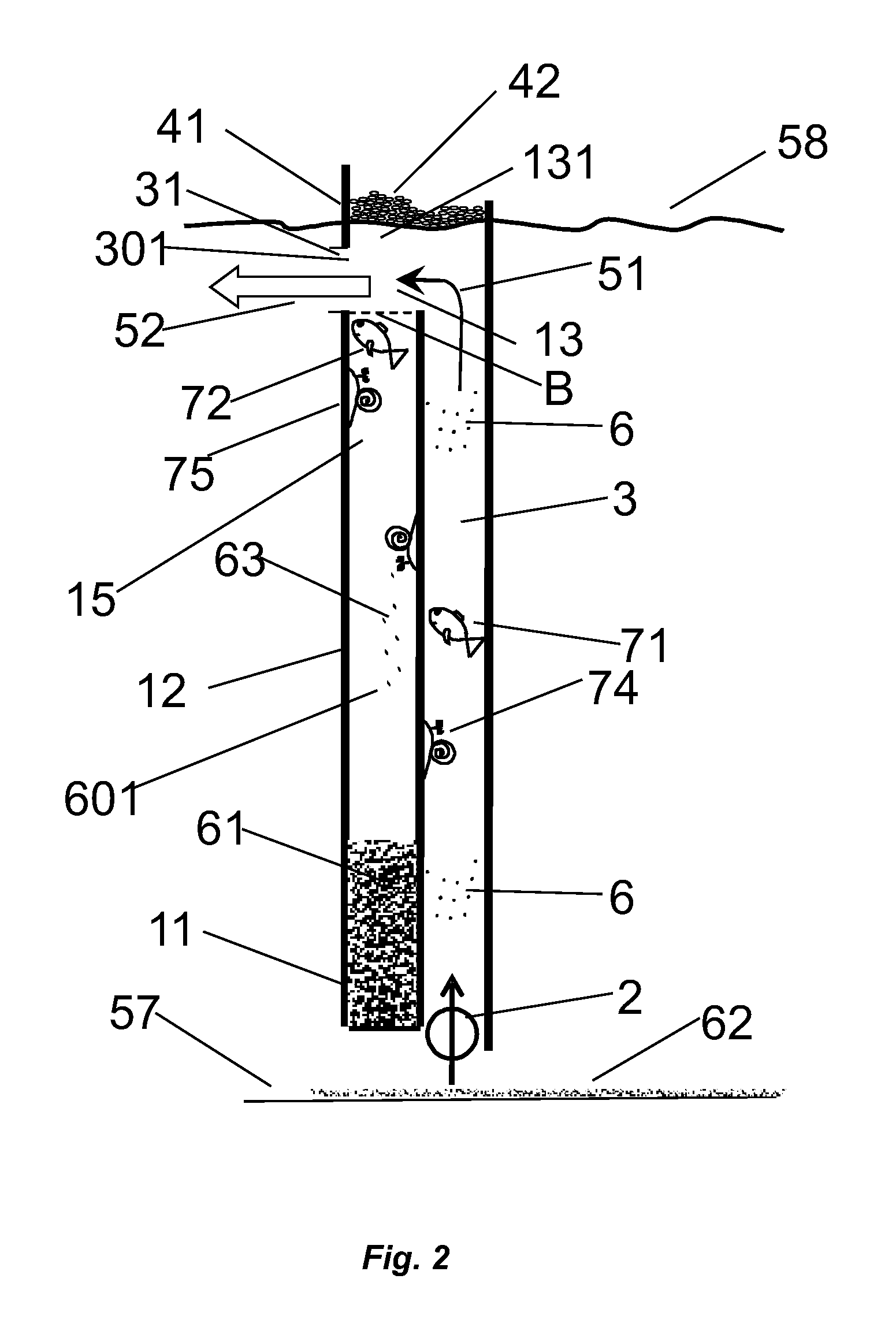
Method for cleaning a water environment of sludge and a device for cleaning a water environment of sludge, in particular an aquarium, miniature decorative pond, or oceanarium
a technology of water environment and cleaning method, which is applied in the direction of gravity filter, loose filtering material filter, stationary filter element filter, etc., can solve the problems of clogging, need for frequent labour-intensive replacement or regeneration, and degeneration of creatures trapped in water environment, so as to save biotical environment components and efficient removal of sludge
- Summary
- Abstract
- Description
- Claims
- Application Information
AI Technical Summary
Benefits of technology
Problems solved by technology
Method used
Image
Examples
example i
[0056]The device solution to be applied in a classic aquarium is illustrated in FIG. 6. The maximally flat structure of the device adjoins and occupies the entire smaller or the entire larger wall of the aquarium tank with walls 59. The water intake has the form of a supply channel 3 slot, running on a small height in water along the entire wall 59, over the substrate layer 571 surface on the water tank bottom, and in addition the distribution member 21 of the driving gas is laid on the substrate 571 surface. Water leaves the chamber 1 through a horizontal slot-like opening of the directing member 35, which directs water upwards. The operation of the device causes a slow horizontal eddy of the rotating stream 55 throughout the whole tank, gently sweeping the resting sludge 62 from the substrate 571 surface towards the water intake through the trap in the same direction as the incoming stream 511.
example ii
[0057]Another solution of the device to be applied in a classic aquarium is illustrated in FIG. 7 and FIG. 8. The flat chamber 1, in the projection designated as structure 102, adjoins and occupies a part of the larger wall of the aquarium with walls 59, up to the corner. The water intake has the form of a slot as an inlet gap 36, running on low height in water along the aquarium wall, over the substrate layer 571 surface on the tank bottom, and in addition the distribution member 21 of the driving gas lies on the substrate 571 surface. Water leaves the chamber 1 through a horizontal slot-like opening of the directing member 37, 372. The directing member 37, 372 directs water tangentially along the upper zone of the bigger aquarium wall 59, which the device adjoins, horizontally towards the place where the aquarium wall 59 is free, that is not occupied by the adjoining device structure. The operation of the device generates a slow twisted geometry eddy of water with swirling sludge ...
example iii
[0058]Another solution of the device may be applied mainly in a square base aquarium. The structure 102, of a triangular vertical projection, occupies a tank corner, particularly in an aquarium like the one shown in FIGS. 9 and 10. The water intake 33 has the form of a hole, located horizontally and elevated above the substrate 571 surface, masked with rock chips 572 placed in the centre of the bottom tank zone. The channel 34 leading water to the supply channel 3 goes horizontally and is buried in the substrate 571. The horizontal section of the leading channel 34 is a mechanically separate unit and ends in the corner with its own outlet, placed horizontally, having a form of a triangular gap in the channel ceiling. The porous distribution member 21 of the driving gas is mounted here. The triangular shape of the gap relates to the triangular inlet 361 opening of the vertical section of the supply channel 3, at the same time in this version constituting the main part of the water dr...
PUM
| Property | Measurement | Unit |
|---|---|---|
| depth | aaaaa | aaaaa |
| depth | aaaaa | aaaaa |
| specific gravity | aaaaa | aaaaa |
Abstract
Description
Claims
Application Information
 - R&D
- Intellectual Property
- Life Sciences
- Materials
- Tech Scout
- Unparalleled Data Quality
- Higher Quality Content
- 60% Fewer Hallucinations
Browse by: Latest US Patents, China's latest patents, Technical Efficacy Thesaurus, Application Domain, Technology Topic, Popular Technical Reports.
© 2025 PatSnap. All rights reserved.Legal|Privacy policy|Modern Slavery Act Transparency Statement|Sitemap|About US| Contact US: help@patsnap.com


