Battery cooling/heating structure and battery module
a cooling/heating structure and battery technology, applied in battery/fuel cell control arrangement, battery/cell components, cell components, etc., can solve the problems of affecting the number of batteries to be loaded, the cooling/heating structure constructed by stacking the heater plate and the cooling plate is increased in size, and the cooling/heating plate cannot be efficiently heated, so as to achieve efficient cooling/heating of the battery and the miniaturization of the cooling/heating structure.
- Summary
- Abstract
- Description
- Claims
- Application Information
AI Technical Summary
Benefits of technology
Problems solved by technology
Method used
Image

Examples
first embodiment
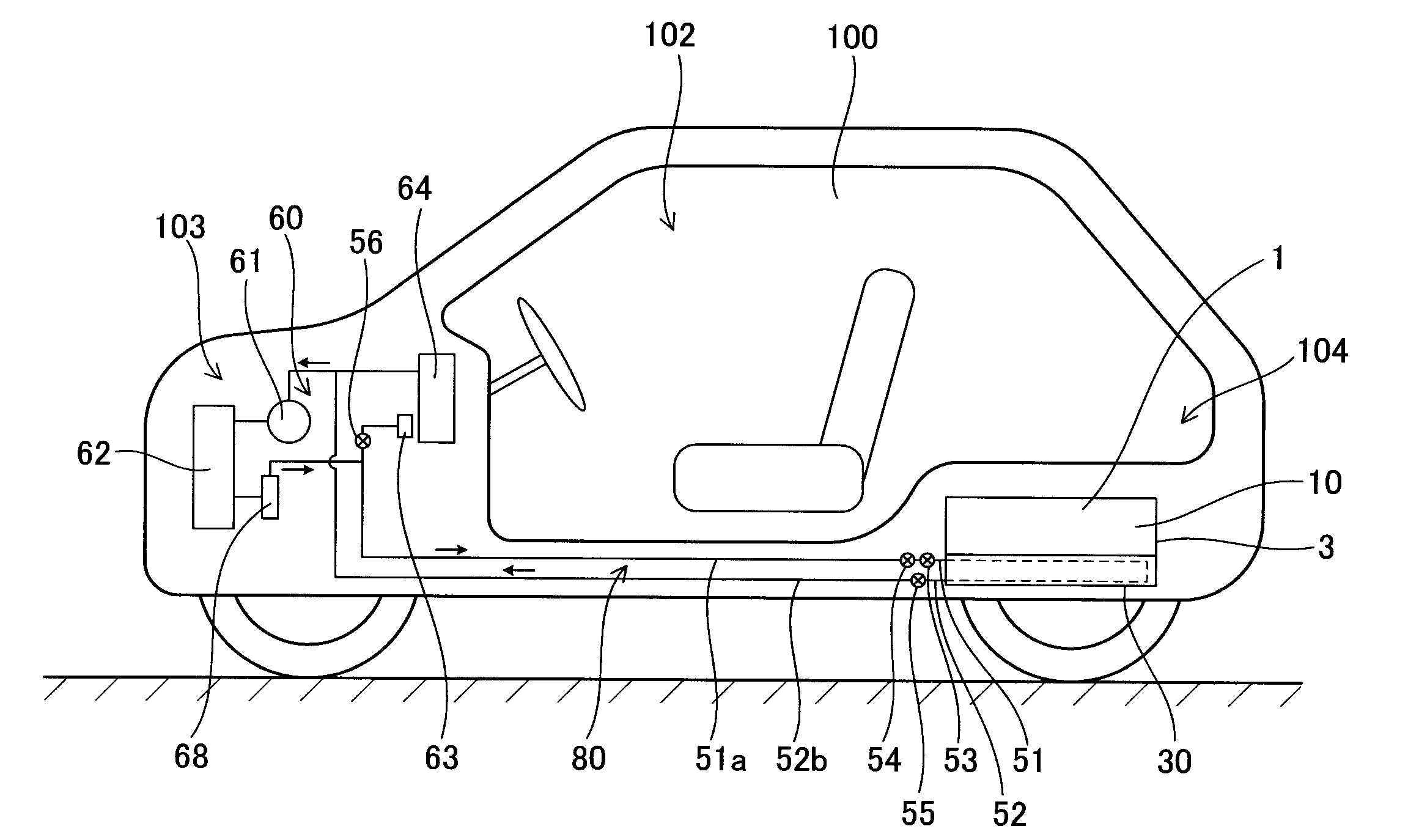
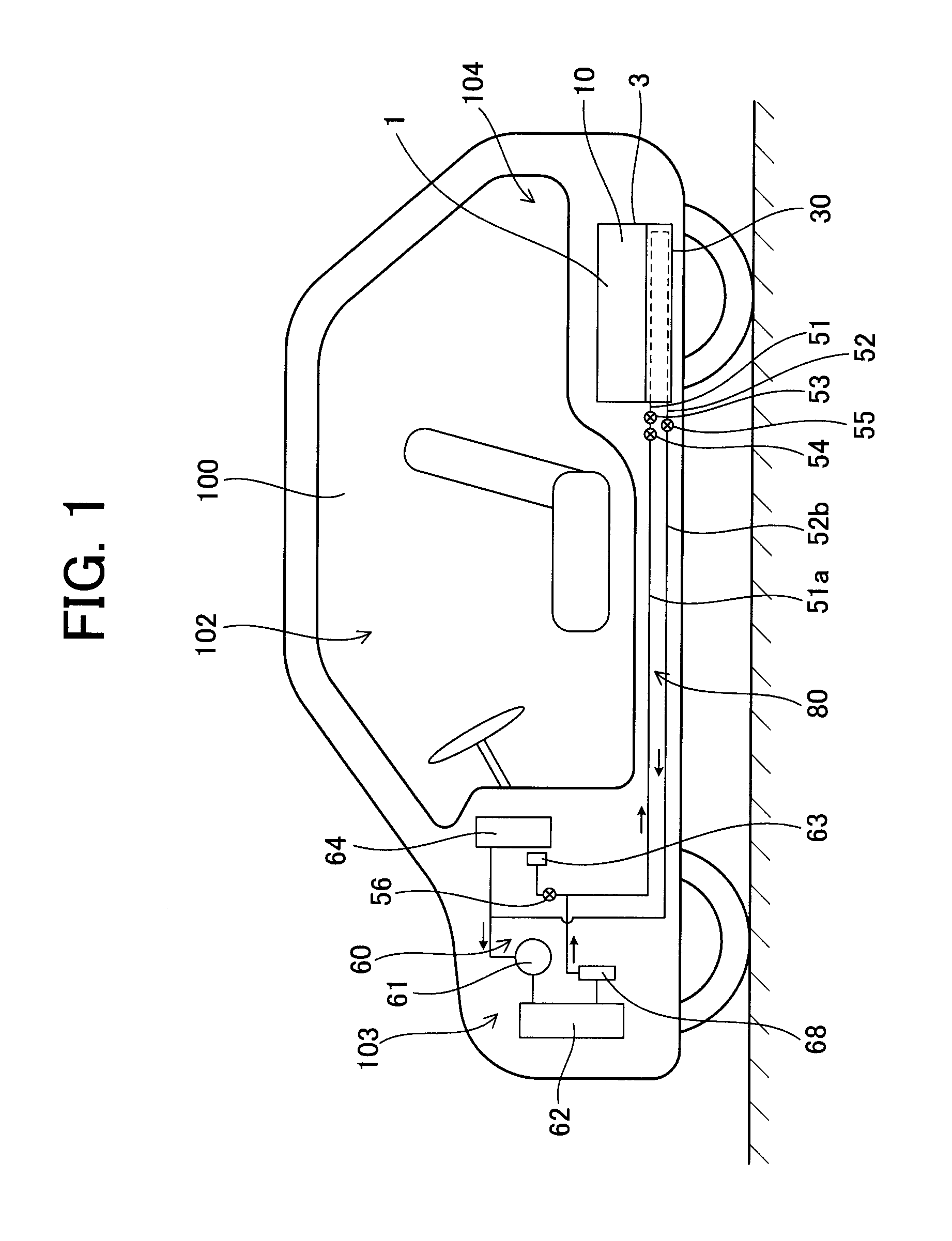
[0039]FIG. 1 shows a vehicle 100 such as a hybrid vehicle, an electrical vehicle or the like in which a battery module 1 according to an embodiment is mounted. The battery module 1 is generally disposed under a floor at the rear side of a rear seat 101, between the rear seat 101 and a trunk room 104, under a floor of the trunk room 104 or the like in which a mount space is easily provided in the vehicle 100. The battery module 1 has an assembled battery 10 and a plate 30 which is brought into contact with the assembled battery 10 to cool / heat the assembled battery 10, and the assembled battery 10 and the plate 30 are accommodated in a case 3 having a substantially hermetically-sealed structure having a side plate and a bottom plate (not shown). The assembled battery 10 is designed in a substantially rectangular parallelepiped shape by arranging and assembling plural electric cells (not shown).
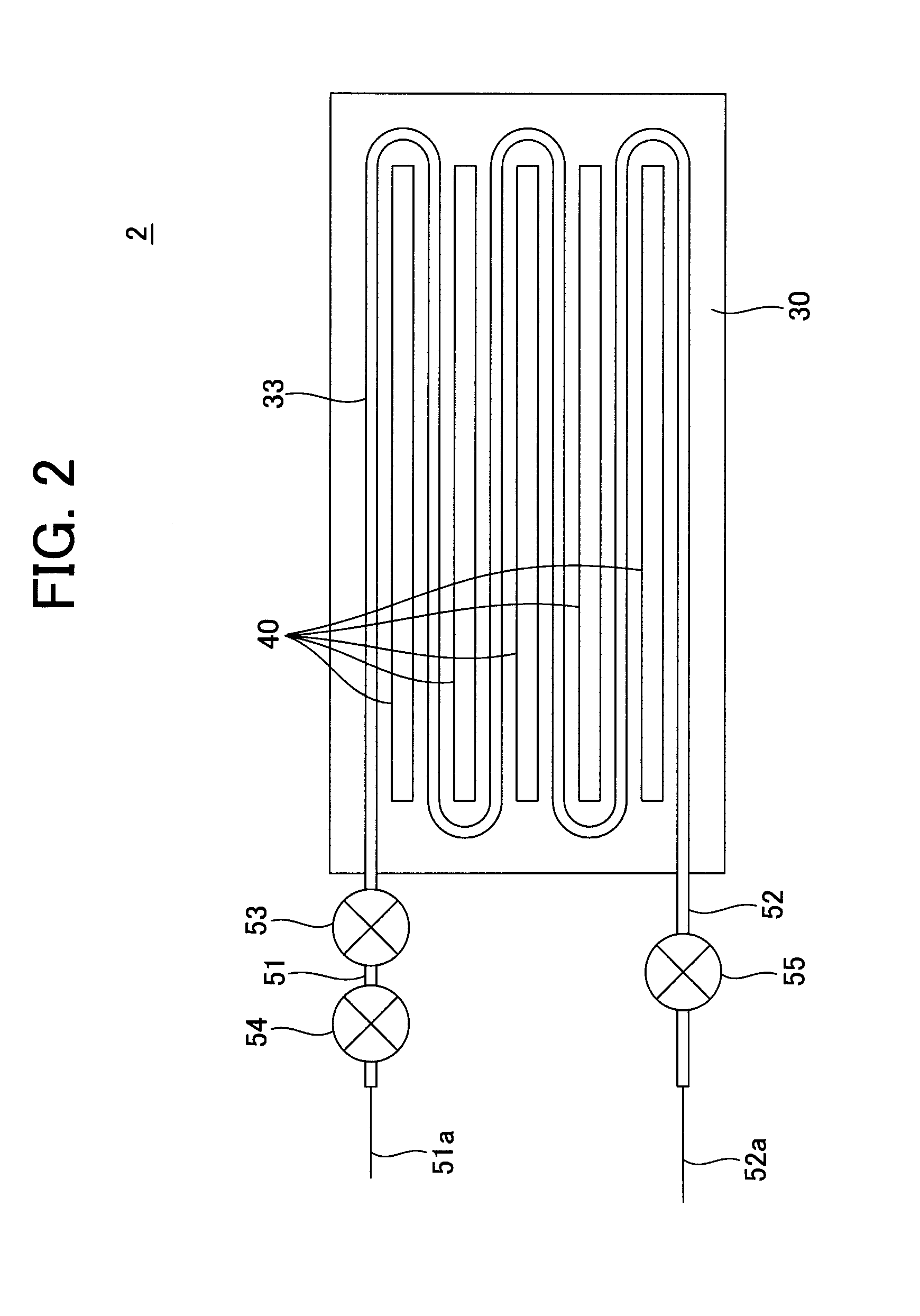
[0040]A medium inlet pipe 51 and a medium outlet pipe 52 intercommunicate with the plate 30...
second embodiment
[0067]FIG. 6 is a circuit diagram showing the cooling cycle of the plate 30 according to a second embodiment. In the following description, the same elements as described with respect to the first embodiment are represented by the same reference numerals, and the description thereof is omitted.
[0068]A refrigeration cycle of this embodiment is not an in-vehicle air-conditioning refrigeration cycle, but a refrigeration cycle 90 which is exclusively provided to the battery cooling / heating structure 2. The refrigeration cycle 90 may be installed to be adjacent to the battery module 1. Therefore, the pipe can be shortened, the routing workability of the refrigerant pipe can be enhanced. In addition, the thermal loss in the pipe can be reduced, and the cooling efficiency of the battery cooling / heating structure 2 can be enhanced.
[0069]The refrigeration cycle 90 has a compressor 74, a condenser 72 and a pressure-reducing device 73 which are connected to the plate 30 through a pipe. The pre...
third embodiment
[0086]FIG. 7 shows a vehicle 100 such as a hybrid vehicle, an electric vehicle or the like which stops on an ascending slope. In the following description, the same elements as described with reference to the first or second embodiment are represented by the same reference numerals, and the description thereof is omitted.
[0087]The battery module 1 has an assembled battery 10, a plate 30 described later which is brought into contact with the assembled battery 10 to cool / heat the assembled battery 10, and a battery cooling / heating structure 2 which is formed integrally with the plate 30. A refrigerant pipe 51a is connected between a receiver tank 68 and a first pressure-reducing device 63 through a first opening / closing valve 54. Furthermore, the refrigerant pipe 52a is connected between the evaporator 64 and the compressor 61 through the second opening / closing valve 55. The refrigerant pipe 51a is connected to the medium inlet pipe 51 through the second pressure-reducing device 53, a...
PUM
 Abstract
Description
Claims
Application Information