
Circuit Tracer

a circuit tracer and circuit breaker technology, applied in the direction of circuit interrupter testing, electrical connection testing, sustainable buildings, etc., can solve the problems of loss of association between the circuit breaker and the electricity outlet, error-prone and costly procedures,

Active Publication Date: 2011-08-25
PANORAMIC POWER
View PDF18 Cites 244 Cited by
  • Summary
  • Abstract
  • Description
  • Claims
  • Application Information

AI Technical Summary

Benefits of technology

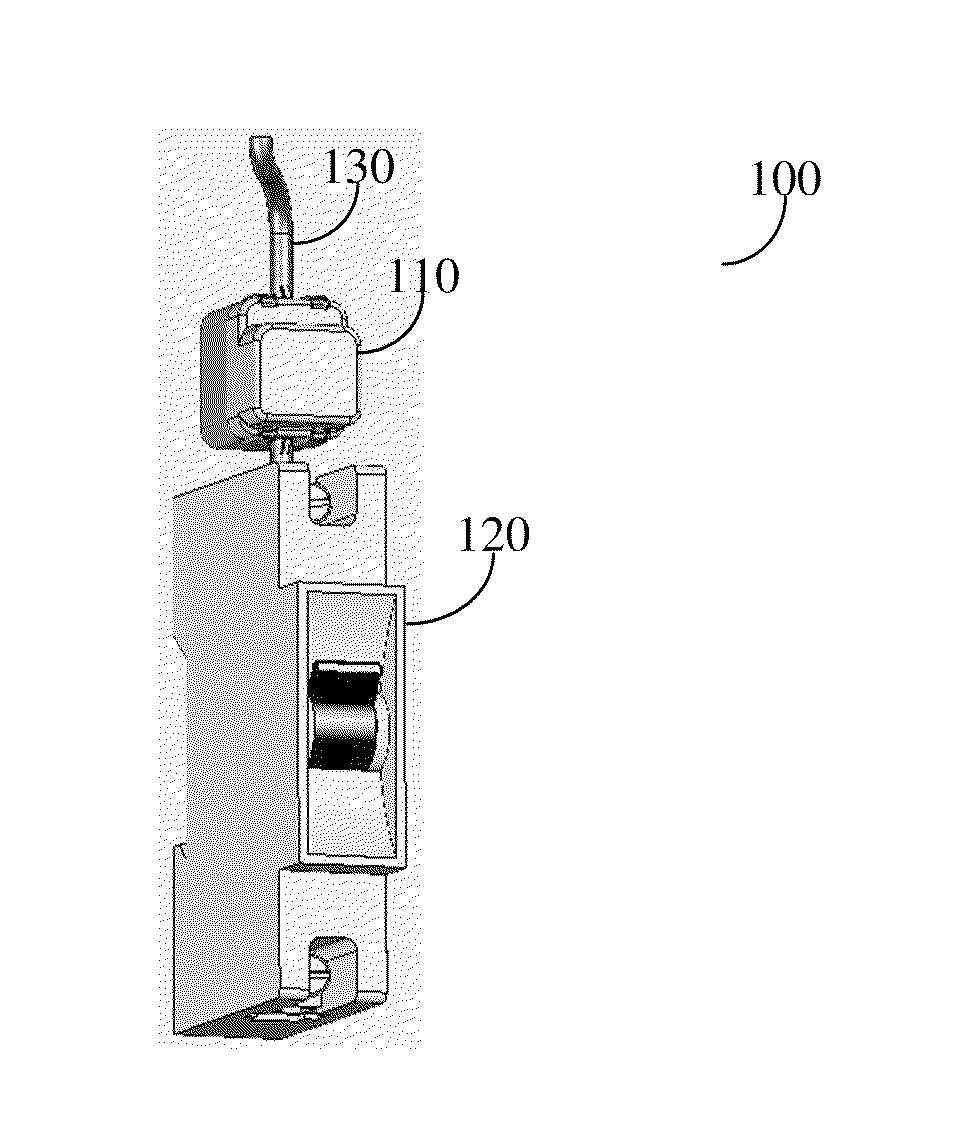
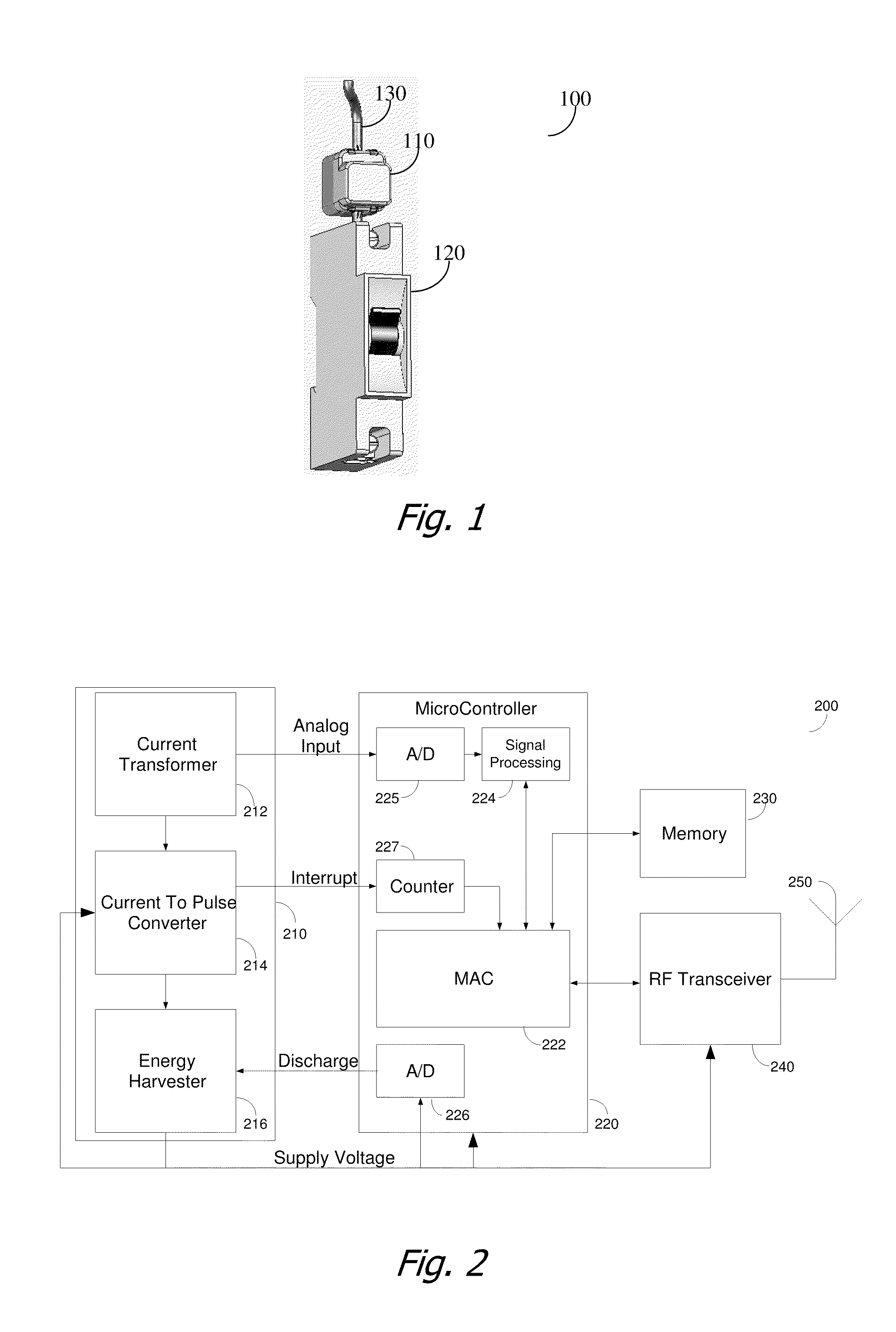
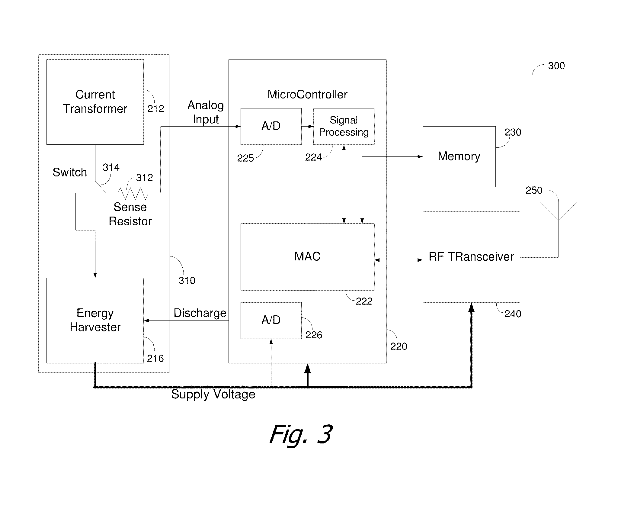
[0013]The circuit tracer combines the use of circuit breakers or power consuming devices equipped with sensors capable of sensing at least a change in the power consumption of the circuit and transmitting, preferably wirelessly, such information. The information is received directly or indirectly by a circuit tracer having a display, the display showing all the circuit breakers and power consuming devices directly equipped with the sensors. Upon changing the load of an electricity outlet, such as a wall outlet, a device connected through an outlet, a device connected directly to the circuit breaker, a device activated by a switch, a light source, HVAC, pump, electrical machinery, etc., the sensor equipped circuit breaker provides an indication of such power or current consumption change to the circuit tracer. This allows the user of the circuit tracer to associate on the circuit tracer the circuit breaker with the specific electricity outlet. The association information may be saved on a central server or database for future use.

Problems solved by technology

In some cases, wall outlets may not be connected to a power consuming device at any given time.
It is not unusual as time passes by that the association between the circuit breaker and electricity outlet is lost.
This is both an error prone and costly procedure.
Typically, the person near the circuit breakers must switch the circuit breaker between its on and off positions, resulting in a disruption to all the electricity outlets associated with the circuit breaker, regardless of whether such electricity outlet is being checked or not.
The first person uses standard current measurement to check the current change on each of the circuit breakers to find the circuit breaker whose current is changed, which is a long and cumbersome process.
However, such small signal solutions are not practical for large currents associated with an AC supply.
However, because the method is deficient as in the case of the presence of strong interference signals, the operation of such a solution is limited.
Moreover, any introduction of, for example, a transformer will result in loss of such modulated signal.
This method may result in frequent misdetection due to leakage of the modulated signal to adjacent wires.

Method used


Image

  • Circuit Tracer
  • Circuit Tracer
  • Circuit Tracer

Examples


Embodiment Construction

[0013]The circuit tracer combines the use of circuit breakers or power consuming devices equipped with sensors capable of sensing at least a change in the power consumption of the circuit and transmitting, preferably wirelessly, such information. The information is received directly or indirectly by a circuit tracer having a display, the display showing all the circuit breakers and power consuming devices directly equipped with the sensors. Upon changing the load of an electricity outlet, such as a wall outlet, a device connected through an outlet, a device connected directly to the circuit breaker, a device activated by a switch, a light source, HVAC, pump, electrical machinery, etc., the sensor equipped circuit breaker provides an indication of such power or current consumption change to the circuit tracer. This allows the user of the circuit tracer to associate on the circuit tracer the circuit breaker with the specific electricity outlet. The association information may be saved...


PUM


Abstract

A circuit tracer for use with circuit breakers equipped with sensors capable of sensing at least a change in the power consumption of the circuit and transmitting, preferably wirelessly, such information. The information is received directly or indirectly by a circuit tracer having a display, the display showing all the circuit breakers equipped with the sensors. Upon changing the load of an electricity outlet, such as a wall outlet, a light source, HVAC, pump, electrical machinery, etc., the sensor equipped circuit breaker provides an indication of such power or current consumption change to the circuit tracer. This allows the user of the circuit tracer to associate on the circuit tracer the circuit breaker with the specific electricity outlet. The association information may be saved on a central server or database for future use.

Description

CROSS-REFERENCE TO RELATED APPLICATIONS[0001]This application claims the benefit of U.S. Provisional Patent Application No. 61 / 306,552 filed Feb. 22, 2010 and is hereby incorporated by reference for all that it contains.BACKGROUND OF THE INVENTION[0002]1. Field of the Invention[0003]The invention generally relates to the measurement of power consumption, and more specifically to the association of an electricity outlet with a respective circuit breaker or association of a power consuming device with a sensor using non-intrusive and self-powered measurement of electrical current flow through the power line, such as the power line of the circuit breaker or a power consuming device.[0004]2. Prior Art[0005]In a typical electricity distribution system, power is provided through a main circuit breaker and a device for measurement of the power consumption of the entire electrical network connected thereto. However, typically, the main power line is then connected to a plurality of smaller ...

Claims


Application Information

Patent Timeline
IPC IPC(8): G01R21/06G06F19/00
CPCG01R31/04H01H9/167Y04S20/14Y02B90/224H01H2300/03G01R31/66Y02B90/20G01R31/327
Inventor SALKA, COREYSHAMIR, ADI
Owner PANORAMIC POWER
Learn More