Memory writing system and method

Inactive Publication Date: 2011-08-25
LAPIS SEMICON CO LTD
View PDF1 Cites 1 Cited by
  • Summary
  • Abstract
  • Description
  • Claims
  • Application Information

AI Technical Summary

Benefits of technology

[0014]According to the memory writing system and the memory writing method of the present invention, the writing data transmitting process and the writing result receiving process are performed in accordance with the optimum data amount obtained by the processing time required fo

Problems solved by technology

However, in the conventional writing system, no consideration is given to writing in an optimum state.
However, in the case where the write data size is too small, data writing by flash writers having already received data may be ended before completion of the write data transmission process, resulting in generation of standby times of those flas

Method used


Image

  • Memory writing system and method
  • Memory writing system and method
  • Memory writing system and method

Examples


Embodiment Construction

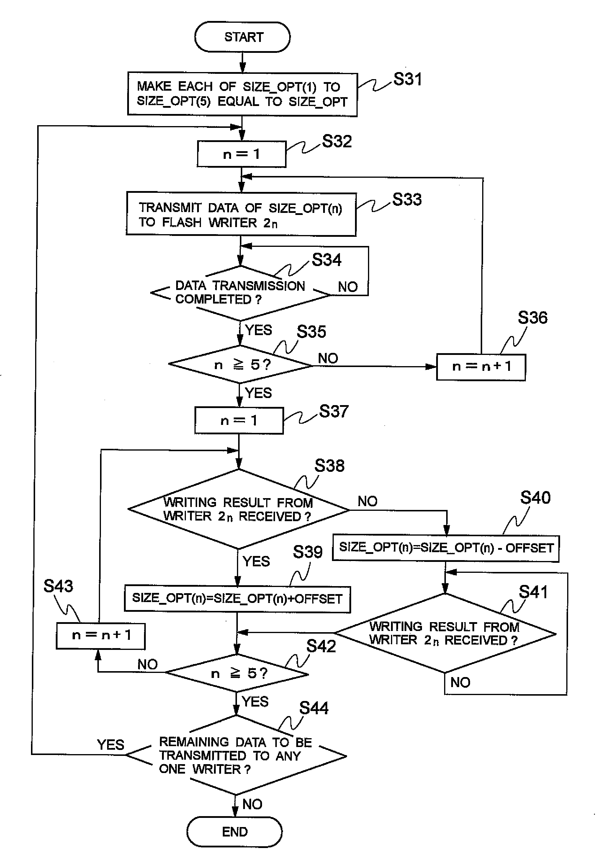
[0023]Now, exemplary embodiments of the present invention will be described in detail with reference to the annexed drawings.

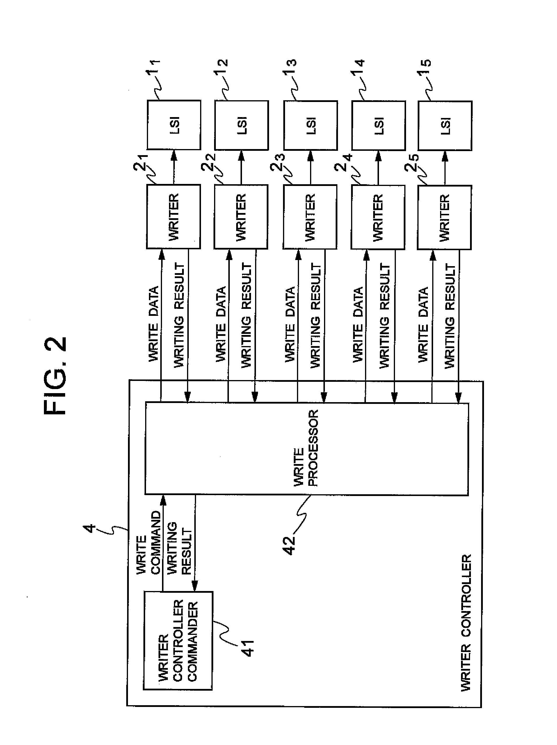
[0024]FIG. 4 shows a memory writing system of the present invention. This memory writing system corresponds to the same five LSIs 11 to 15, each having a flash memory, and includes flash writers 21 to 25, a distributor 3, and a writer controller 4, similarly to the system shown in FIG. 1.

[0025]The writer controller 4 includes a writer controller commander 41, a write processor 42, and a processing time measurer 43. The writer controller commander 41 controls the write processor 42 and the processing time measurer 43. The writer controller commander 41 generates commands including a write command to the write processor 42 such that the write processor 42 transmits data of the maximum size MAX_SIZE to each flash writer, and receives a writing result from each flash writer. The write processor 42 sequentially supplies write data to the flash writers 21 to 25 in r...


PUM


Abstract

Memory writing system and method determining an optimum data amount per one-time data transmission to one memory writer to enable optimization of communication efficiency and write speed, include: setting the amount of data to be transmitted per one-time transmission from a writer controller to different values for respective memory writers; transmitting data of each of the data amounts from the writer controller to a corresponding one of the memory writers; measuring, for each of the data amounts, a processing time required for the writer controller to transmit data to the corresponding memory writer and a data write time of the corresponding memory writer; obtaining, for each of the data amounts, a correlation between the processing time and the data write time based on respective measured values; setting an optimum data amount based on the correlation to satisfy a desired data write time condition; and, after the optimum data amount is set, sequentially transmitting data of the optimum data amount from the writer controller to the memory writers.

Description

BACKGROUND OF THE INVENTION[0001]1. Field of the Invention[0002]The present invention relates to a system and method for writing data into nonvolatile memories, such as flash memories.[0003]2. Description of the Related Art[0004]For mass production of large scale integrated circuits (LSIs) equipped with flash memories, a writing system is constructed on a part of a production line to write data, such as programs, into the flash memories. The writing system may be automated, but to do so is costly. For this reason, in the case where the number of LSIs to be produced can be manually coped with, a conventional writing system may be constructed as shown in FIG. 1.[0005]In the writing system of FIG. 1, LSIs 11 to 1n, each equipped with a flash memory, are one-to-one connected to flash writers 21 to 2n, respectively. Each of the flash writers 21 to 2n is connected to one writer controller 4 via a distributor 3. The writer controller 4 holds data to be written into each of the LSIs 11 to 1...

Claims


Application Information

Patent Timeline
IPC IPC(8): G06F12/00
CPCG06F12/0246
Inventor UCHIDA, WATARU
Owner LAPIS SEMICON CO LTD
Why Eureka
Try Eureka