
Coriolis mass flowmeter

a mass flowmeter and coriolis technology, applied in the field of coriolis mass flowmeters, can solve the problems that the damage of the coriolis mass flowmeter cannot be ruled out, the magnetic field is negatively influenced by this type of mounting screw, etc., and achieves the effect of facilitating installation, less force, and further simplified installation

Active Publication Date: 2011-09-01
KRONE GMBH
View PDF2 Cites 11 Cited by
  • Summary
  • Abstract
  • Description
  • Claims
  • Application Information

AI Technical Summary

Benefits of technology

[0007]It is thus provided according to the invention, that the permanent magnet is inserted in a device provided solely for its mounting, namely the magnet holder. For this reason, the permanent magnet is at least partially enclosed by the magnet holder according to the invention, which acts as protection against external influences, such as bumping. Furthermore, the fixation of the permanent magnet is realized by the magnet holder at least partially enclosing it, so that the permanent magnet does not need to be provided with a hole for the mounting screw.
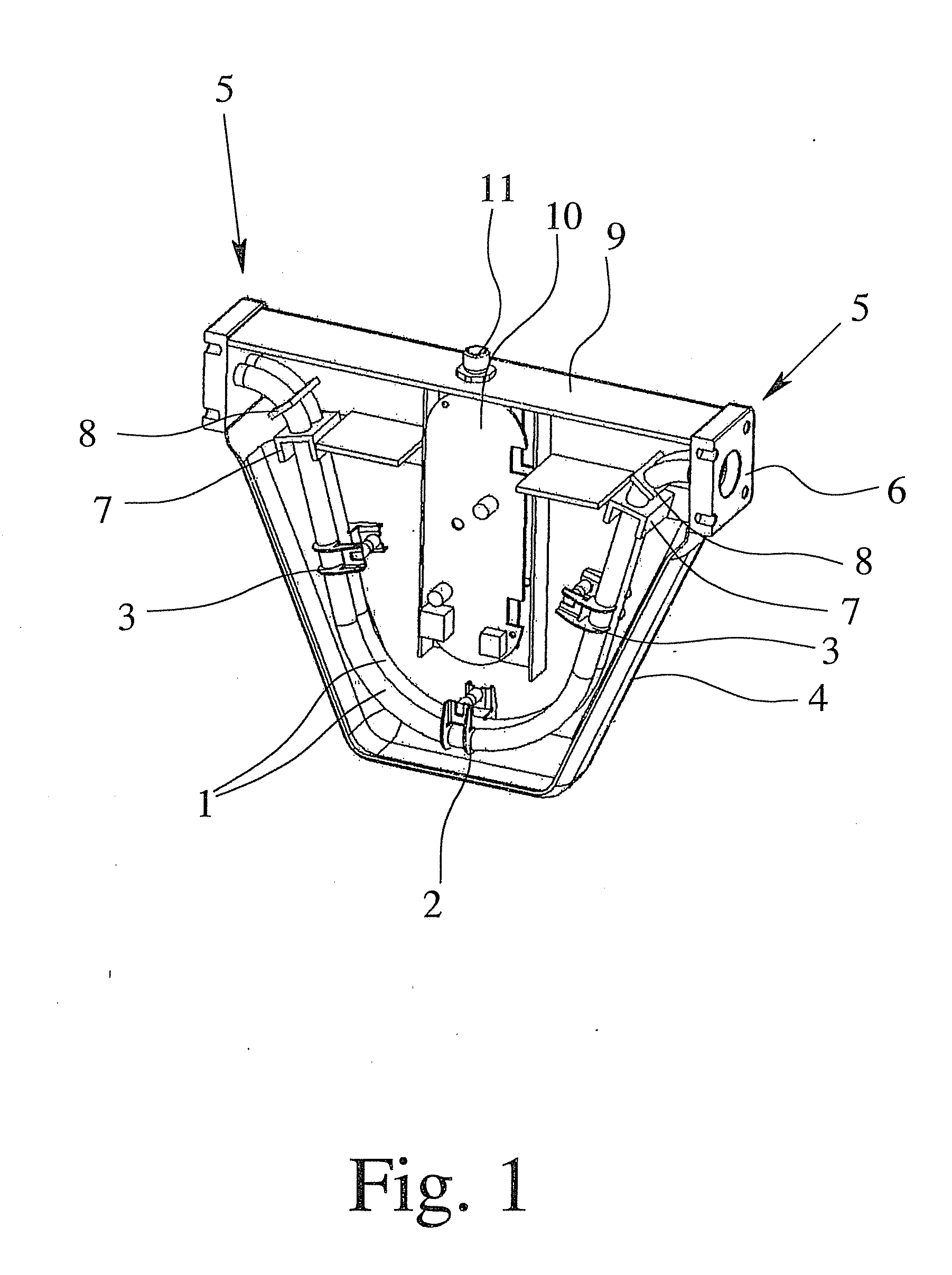
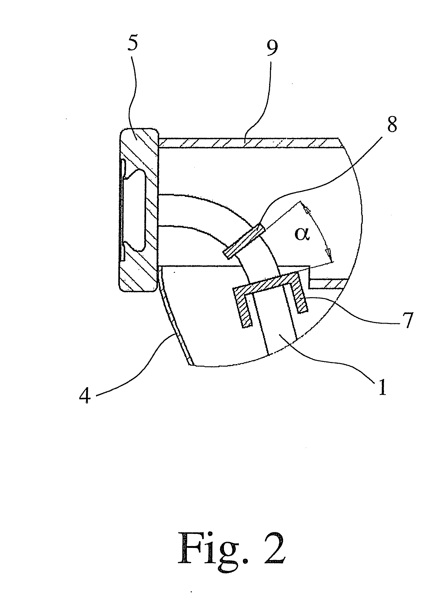
[0036]According to this aspect of the invention, it is also provided that such an optimized angle is provided between both planes of the oscillation node plates that minimum vibrations of the measuring tube are achieved. The coupling between the oscillation of the measuring tube and the oscillation of the process pipeworks result, namely, from these vibrations and thus, better oscillation isolation can be achieved.

Problems solved by technology

However, the magnetic field is negatively influenced by this sort of mounting screw.
In addition, the permanent magnet is exposed practically without any defense mechanism to mechanical external influences such as bumping during transport or during installation, so that damage of the Coriolis mass flowmeter cannot be ruled out.

Method used


Image

  • Coriolis mass flowmeter
  • Coriolis mass flowmeter
  • Coriolis mass flowmeter

Examples


Embodiment Construction

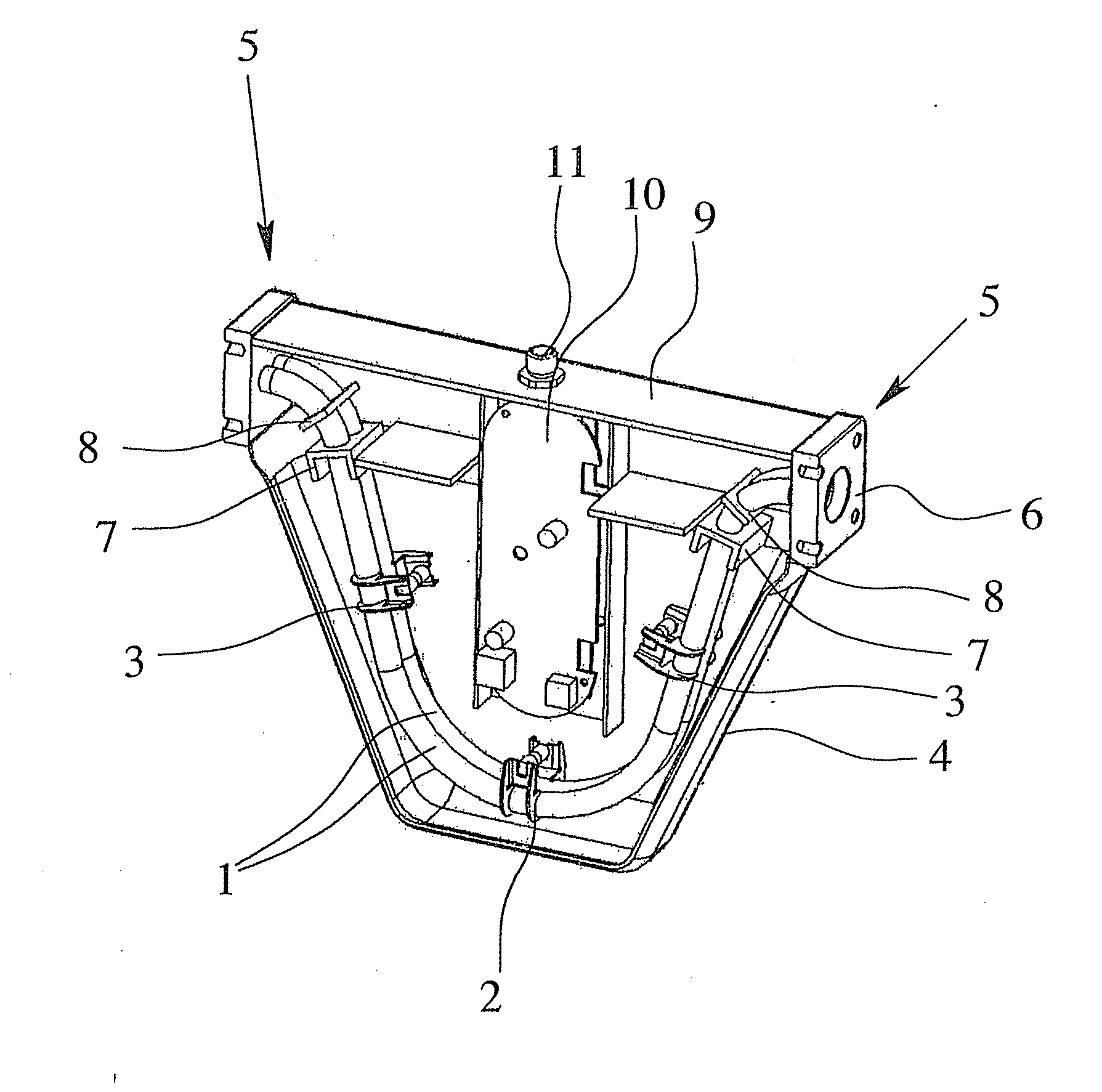
[0046]A Coriolis mass flowmeter according to a preferred embodiment of the invention can be seen in FIG. 1 that has two measuring tubes 1 that can be excited to oscillation, an oscillation driver 2 and two oscillation sensors 3. Both measuring tubes 1 run parallel to one another in a housing 4 of the Coriolis mass flowmeter and, in fact, in total have an essentially U-shaped course. An end connection plate and adapter 5 is provided on each end of the measuring tube 1, which, on the one hand, allows for access to the process pipeworks in which the Coriolis mass flowmeter is installed, namely using a flanged connection 6, and, on the other hand, allows for the connection of one pipe of the process pipeworks to both measuring tubes 1, i.e. serves as a flow splitter. It is essential here that the end connection and adapter plate 5 is made of one common component.

[0047]Two neighboring oscillation node plates 7, 8 are provided on the ends of the measuring tube 1. At the same time, a devic...


PUM


Abstract

A Coriolis mass flowmeter having two measuring tubes, wherein two neighboring oscillation node plates are provided on one end of the measuring tube that connect the two measuring tubes to one another and wherein the angle between the planes of both oscillation node plates is determined in such a manner that the vibration of the measuring tubes is minimal up to a predetermined driving force. A method of producing the flowmeter is also disclosed.

Description

CROSS-REFERENCE TO RELATED APPLICATIONS[0001]The present application is a division of Ser. No. 12 / 108,750, filed on Apr. 21, 2008, now U.S. Pat. No. ______.BACKGROUND OF THE INVENTION[0002]The invention relates to a Coriolis mass flowmeter with a measuring tube that can be excited into oscillation, an oscillation driver and / or an oscillation sensor, wherein the oscillation. driver and / or the oscillation sensor has a permanent magnet.[0003]Mass flowmeters that work according to the Coriolis principle generally have at least one oscillation driver that excites the measuring tube into oscillation as well as two oscillation sensors, which register the achieved oscillation of the measuring tube. The determination of the mass flow is then definable, e.g. using the phase shift of the achieved oscillations between the two oscillation sensors.[0004]The oscillation driver and oscillation sensors are generally assembled in such a manner that they have a permanent magnet as well as a magnetic c...

Claims


Application Information

Patent Timeline
Patent Type & Authority Applications(United States)
IPC IPC(8): G01F1/84
CPCG01F1/8413G01F1/8404G01F1/8477
Inventor HUSSAIN, YOUSIFWANG, TAOROLPH, CHRISHARRISON, NEIL
Owner KRONE GMBH
Learn More