Artificial ventilation apparatus

a ventilation apparatus and artificial technology, applied in mechanical devices, valves, respirators, etc., can solve the problems of alarm malfunction, inability to detect the disconnection of the connecting portion, and serious affecting the patient, so as to reduce the number of parts that can be easily attached and detached, and improve the safety.

Active Publication Date: 2011-09-01
NIHON KOHDEN CORP
View PDF13 Cites 8 Cited by
  • Summary
  • Abstract
  • Description
  • Claims
  • Application Information

AI Technical Summary

Benefits of technology

[0014]It is therefore an object of the invention to provide an artificial ventilation apparatus in which the number of portions that can be easily attached and detached is decreased, so

Problems solved by technology

However, some of simple ventilators which are operated manually or by an additional pressure source or the like do not include a power supply portion.
Particularly, there is a possibility that disconnection of an inspiratory circuit portion may seriously affect the patient.
Therefore, there is a very cumbersome problem in that it is necessary to check that the carbon dioxide concentration sensor 84 and the like are surly attached, so that a ventilation failure in the patient due to disconnection of a connecting portion, malfunction of the alarm due to disconnection of the sensor, a ventilation failure in the patient due to the malfunction, or the like does not occur.
This may cause malfunction of an alarm or the like.
However, the carbon dioxide concentration sensor 84 detects carbon dioxide produced by spontaneous respiration of the patient, and hence the disconnection cannot be detected by the carbon dioxide concen

Method used


Image

  • Artificial ventilation apparatus
  • Artificial ventilation apparatus
  • Artificial ventilation apparatus

Examples


first embodiment

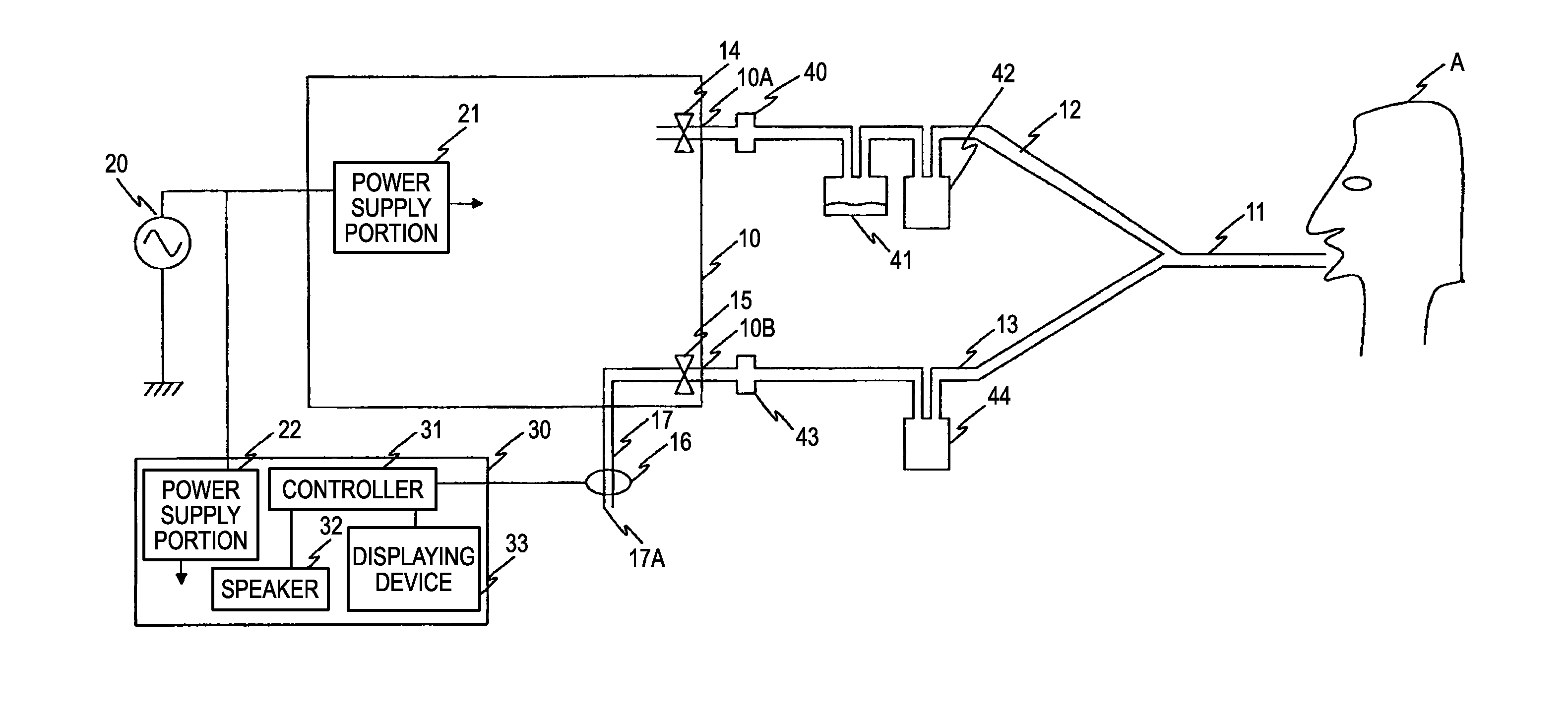
[0031]Hereinafter, embodiments of the artificial ventilation apparatus of the invention will be described with reference to the accompanying drawings. In the figures, the identical components are denoted by the same reference numerals, and duplicated description will be omitted. FIG. 1 shows the configuration of an artificial ventilation apparatus of a The artificial ventilation apparatus includes a ventilator 10 which outputs a gas having a required oxygen concentration for artificial ventilation, at a required pressure.

[0032]A connecting portion 11 which is connected to the respiratory system of the patient A is attached to the respiratory system. The connecting portion 11 is configured by a mask, a conduit tube intubated into the trachea, or the like. An inspiratory circuit 12 which is a flow path for flowing the gas from the ventilator 10 to the connecting portion 11 connects between a gas outlet 10A of the ventilator 10 and the connecting portion 11. In the inspiratory circuit...

second embodiment

[0046]FIG. 5 shows the configuration of an artificial ventilation apparatus of a In the artificial ventilation apparatus, a ventilator 110 includes a controlling portion 25. The controlling portion 25 is similar to a corresponding related-art portion, i.e., controls the operation of the apparatus based on biological information of the patient A and apparatus information of the apparatus, monitors the patient A and the apparatus to display required parameters, and, in case of abnormality, generates an alarm. The biological information means information related to the living body, such as the arterial oxygen saturation, the blood pressure, the body temperature, the respiratory rate, and the airway pressure. In FIG. 5, only a pressure sensor 26 which is disposed in the connecting portion 11 in order to obtain information of the airway pressure is shown.

[0047]The apparatus information of the apparatus is operation information of the ventilator 110, information such as the pressure and ...


PUM


Abstract

An artificial ventilation apparatus includes: a connecting portion which is connected to a respiratory system of a patient; an inspiratory circuit which is a flow path for flowing a gas from a ventilator to the connecting portion; an expiratory circuit which is a flow path for guiding a gas exhausted from the connecting portion to an exhaust portion of the ventilator; an expiratory valve which blocks a flow of a gas from the exhaust portion toward the connecting portion; a carbon dioxide concentration sensor which is disposed in a circuit that is provided at a downstream side of the expiratory valve and which detects a carbon dioxide concentration; and an alarm outputting unit which outputs an alarm based on an output of the carbon dioxide concentration sensor.

Description

BACKGROUND OF THE INVENTION[0001]The present invention relates to an artificial ventilation apparatus including a carbon dioxide concentration sensor.[0002]An artificial ventilation apparatus is equipped with functions of detecting a non- or hypo-ventilated state of the patient due to malfunction of a ventilator or an abnormality of a respiratory circuit, and generating an alarm. Particularly, it is said that End-tidal CO2 (EtCO2) monitoring is useful because it is possible to check that the patient actually performs gas exchange.[0003]An EtCO2 measuring mechanism mounted on an artificial ventilation apparatus or on a patient monitoring apparatus other than an artificial ventilation apparatus is configured as shown in FIG. 4.[0004]The apparatus shown in FIG. 4 is a related-art artificial ventilation apparatus, and configured in the following manner. A ventilator 80 is connected to the respiratory system of the patient A through an inspiratory valve 82 which is a one-way valve, an in...

Claims


Application Information

Patent Timeline
IPC IPC(8): A61M16/00
CPCA61M16/0051A61M16/107A61M16/1055A61M16/208A61M2016/0027A61M2205/502A61M2205/581A61M2205/583A61M2230/205A61M2230/30A61M2230/42A61M2230/432A61M2230/50A61M16/1065A61M16/0808A61M16/085A61M16/021
Inventor USUDA, YUTAKAKOBAYASHI, NAOFUMIYAMAMORI, SHINJINAGAI, YASUSHI
Owner NIHON KOHDEN CORP
Why Eureka
Try Eureka