Multi-LED Control

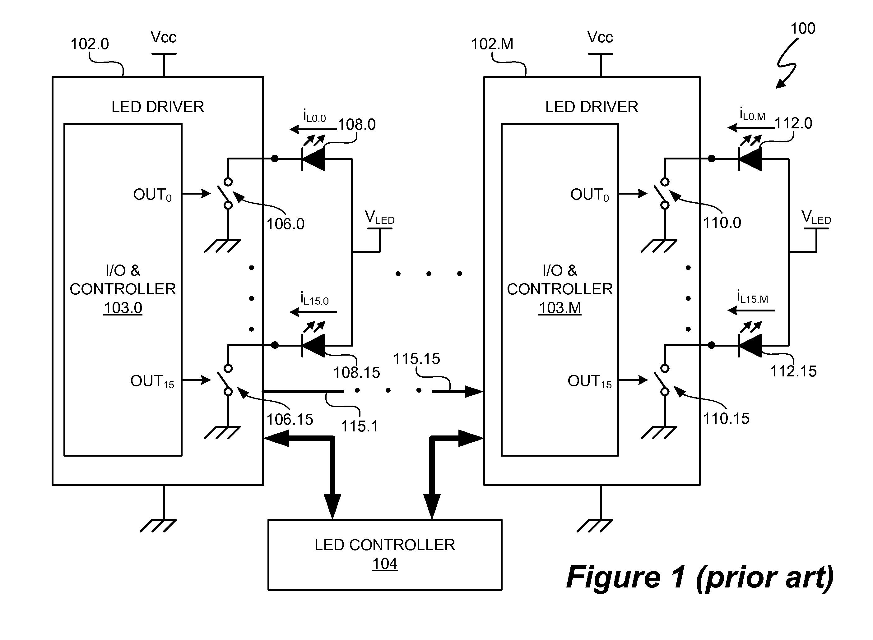
a technology of led control and driver, applied in the field of electronic and lighting, can solve the problems of low system efficiency of the led driver and controller system b>100/b>

Active Publication Date: 2011-09-01
SIGNIFY HLDG BV
View PDF90 Cites 58 Cited by
  • Summary
  • Abstract
  • Description
  • Claims
  • Application Information

AI Technical Summary

Benefits of technology

[0014]a second switch control signal to control a duty cycle of a second switch coupled to at least a second LED to vary a relative intensity of the first and second LEDs, wherein the first LED is coupled in series with the second LED.
[0015]In another embodiment of the present invention, a method for controlling multiple, series coupled light emitting diodes (LEDs) includes generating a first switch control signal to control a duty cycle of a first switch coupled in parallel across at least a first LED. The method also includes generating a second switch control signal to control a duty cycle of a second switch coupled to at least a second LED to vary a relative intensity of the first and second LEDs, wherein the first LED is coupled in series with the second LED.

Problems solved by technology

Thus, LED driver and controller system 100 generally has a low system efficiency.

Method used


Image

  • Multi-LED Control
  • Multi-LED Control
  • Multi-LED Control

Examples


Embodiment Construction

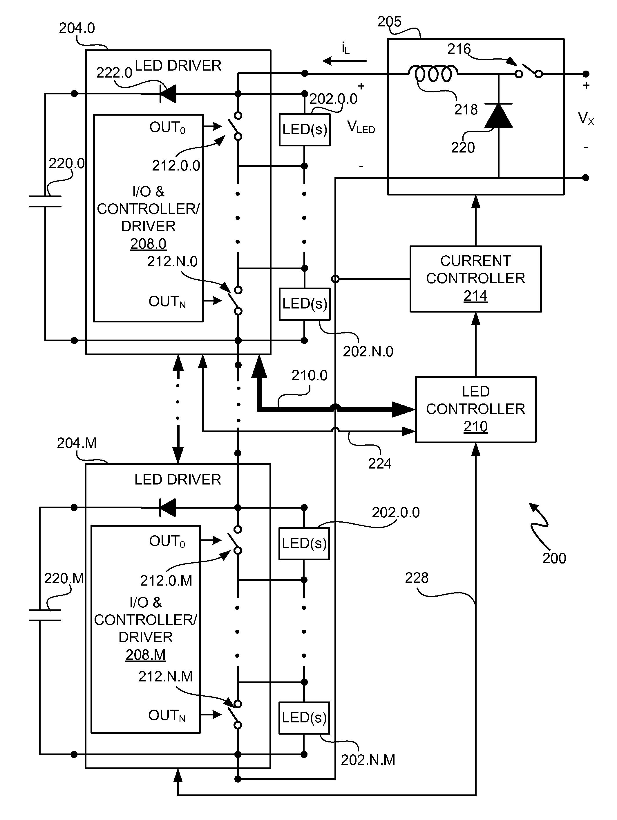
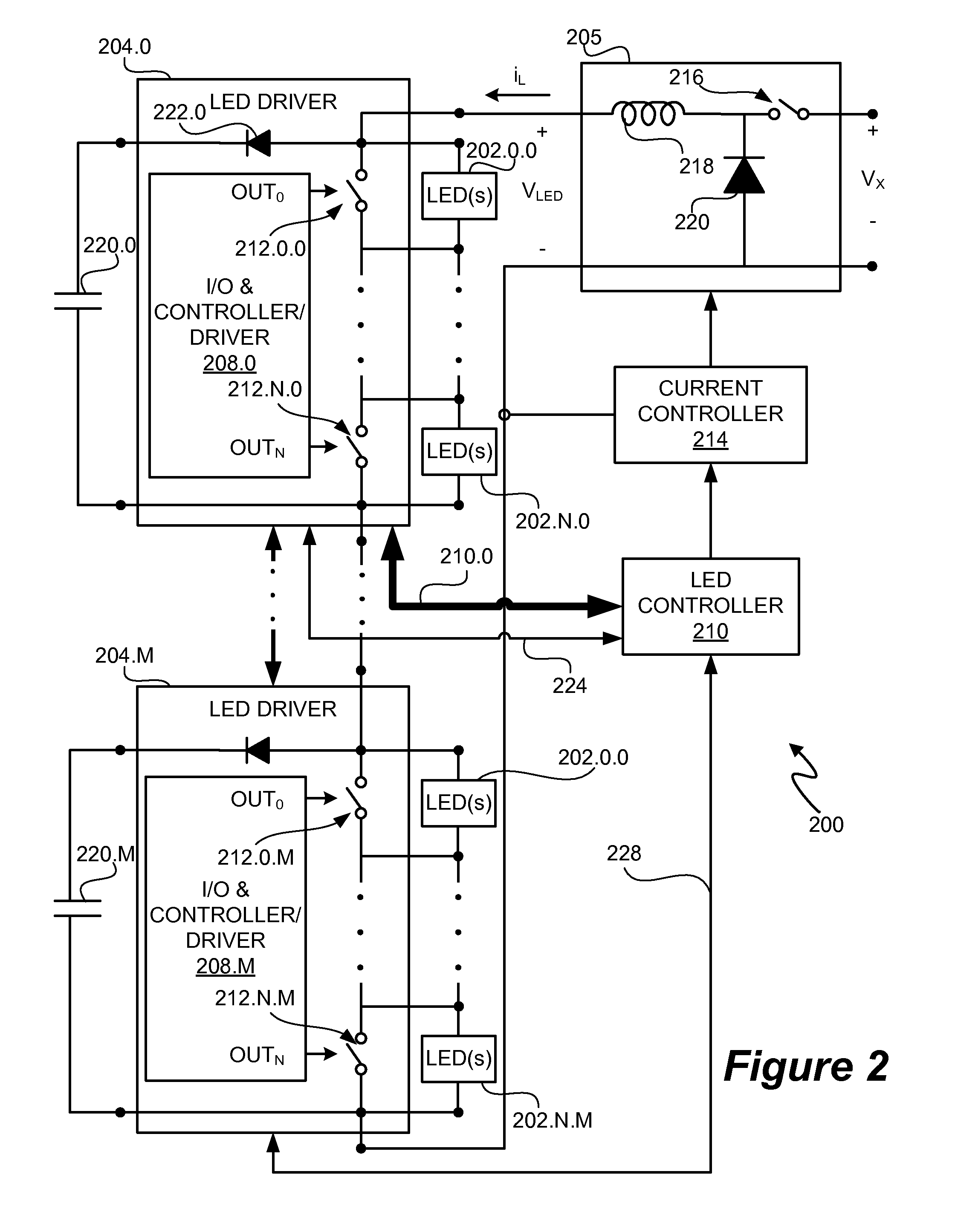
[0023]A LED driver and controller system utilizes switches to parallel connect to respective sets of one or more LEDs and a current source to provide efficient control of the LEDs. In at least one embodiment, the LEDs are connected in series. An LED controller of the LED driver and controller system 200 controls conductivity of the switches. In at least one embodiment, the LED controller provides control signals to one or more LED drivers. The LED drivers receive the control signals and, in response to the control signals, control the conductivity of each switch. In at least one embodiment, the conductivity of the each switch is controlled using a duty cycle modulated control signal. In at least one embodiment, the duty cycle modulated control signal is a pulse width modulated control signal. In another embodiment, the duty cycle modulated control signal is a pulse density modulated control signal.

[0024]Because each switch is connected in a parallel to one or more LEDs, when the swi...


PUM


Abstract

A LED driver and controller system utilizes switches to parallel connect to respective sets of one or more LEDs and a current source to provide efficient control of the LEDs. In at least one embodiment, the LEDs are connected in series. An LED controller of the LED driver and controller system 200 controls conductivity of the switches. In at least one embodiment, the LED controller provides control signals to one or more LED drivers. The LED drivers receive the control signals and, in response to the control signals, control the conductivity of each switch. In at least one embodiment, the conductivity of the each switch is controlled using a duty cycle modulated control signal. In at least one embodiment, the duty cycle modulated control signal is a pulse width modulated control signal. In another embodiment, the duty cycle modulated control signal is a pulse density modulated control signal.

Description

CROSS REFERENCE TO RELATED APPLICATIONS[0001]This application claims the benefit under 35 U.S.C. §119(e) and 37 C.F.R. §1.78 of U.S. Provisional Application No. 60 / 957,753, filed Aug. 24, 2007 and entitled “Multi-LED Control.” U.S. Provisional Application No. 60 / 957,753 includes exemplary systems and methods and is incorporated by reference in its entirety.BACKGROUND OF THE INVENTION[0002]1. Field of the Invention[0003]The present invention relates in general to the field of electronics and lighting, and more specifically to a system and method to controlling and / or providing power to current regulated light sources, such as light emitting diode light sources.[0004]2. Description of the Related Art[0005]Commercially practical incandescent light bulbs have been available for over 100 years. However, other light sources show promise as commercially viable alternatives to the incandescent light bulb. Light emitting diodes (LEDs) are becoming particularly attractive as main stream light...

Claims


Application Information

Patent Timeline
Patent Type & Authority Applications(United States)
IPC IPC(8): H05B37/02H05B44/00
CPCH05B33/0815Y02B20/347H05B33/083H05B45/48Y02B20/30H05B45/375H05B45/3725
Inventor MELANSON, JOHN L.
Owner SIGNIFY HLDG BV
Why Eureka
Try Eureka