Finger-worn device and interaction methods and communication methods

a technology of finger-worn devices and communication methods, applied in the field of humancomputer interaction, can solve problems such as bulky use and discomfort, and achieve the effect of facilitating results

Inactive Publication Date: 2011-09-01
RINGBOW LTD
View PDF30 Cites 274 Cited by
  • Summary
  • Abstract
  • Description
  • Claims
  • Application Information

AI Technical Summary

Benefits of technology

[0014]The invention further provides, in various embodiments, systems in which finger-worn devices may be utilized to control or influence interfaces of touch-screens without fingers touching said touch-screens. More specifically, in some embodiments, finger-worn devices may be utilized for interactions which may precede or follow touch-interactions. Further provided by the invention are various systems in which finger-worn devices may be utilized to estimate the general locations of tips of fingers wearing said finger-worn devices. Further yet provided by the invention are various systems which include touch-screens, and methods for interacting with touch-screens, which can facilitate results similar to utilizing finger-worn devices to estimate the general locations of fingers.

Problems solved by technology

However, such devices include unnecessary elements and features which render them bulky and uncomfortable to use, whereas some of said features find better alternatives in other technologies such as touch-screens and visual-recognition which, as the invention suggests, may be adapted to be used (or “interacted with”) in collaboration with operating finger-worn devices.

Method used


Image

  • Finger-worn device and interaction methods and communication methods
  • Finger-worn device and interaction methods and communication methods
  • Finger-worn device and interaction methods and communication methods

Examples


embodiment 110

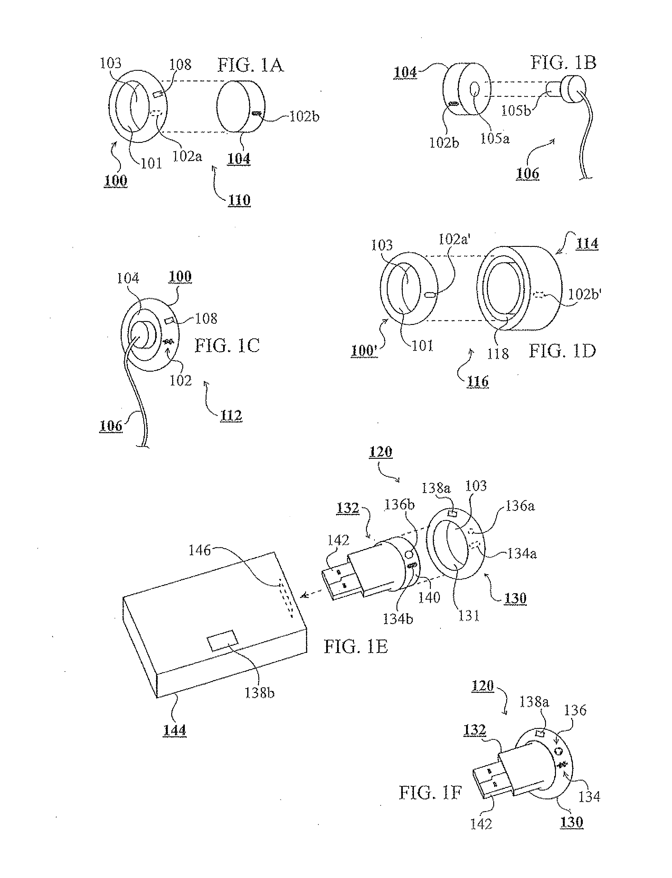
[0108]FIG. 1A shows an embodiment 110 of the invention which may include a device 100 and a plug 104 which may fit into device 100 (shown in the figure device 100 and plug 104 as separated, yet it is made clear that plug 104 may fit into device 100). Plug 104 may be a device, or a section thereof, shaped as a plug. For example, plug 104 may be an adapter generally shaped as a plug. Device 100 may be a device which may be worn on a finger (or simply a “finger-worn device”). More specifically, device 100 may be an input device (e.g. remote-control) that can be worn on a human finger by having a cavity 103 that is fitted for a human finger, such as a hole in an enclosure of device 100 into which a finger can be inserted for wearing the device on said finger.

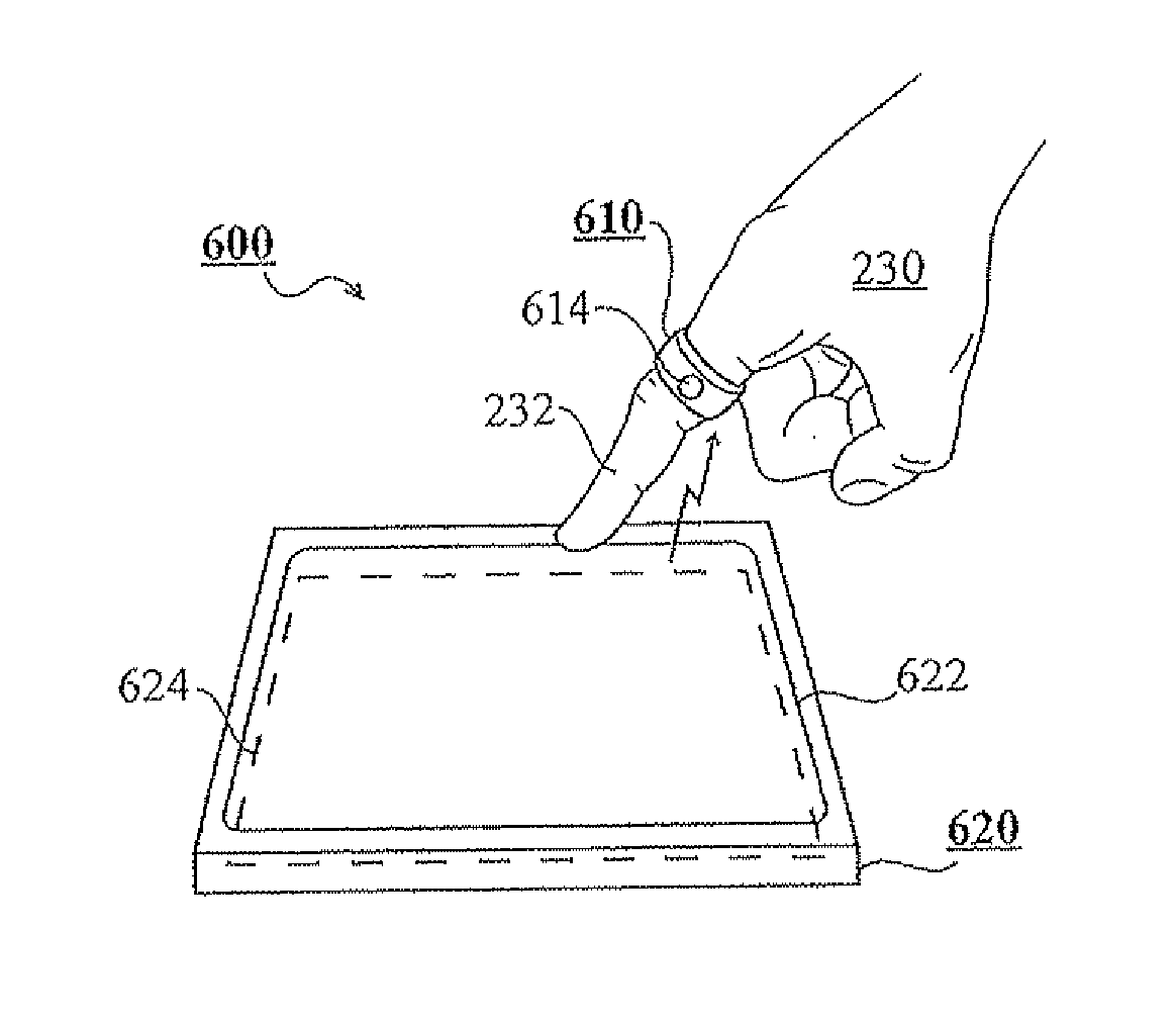
[0109]In some embodiments, device 100 can be operated, such as for registering input, by a thumb of the same hand of the finger wearing the device (see ref. FIG. 2C for a thumb 234 operating a finger-worn device 200). For example, a...

embodiment 116

[0127]FIG. 1D shows an embodiment 116 of the invention which may include a finger-worn device 100′ similar to device 100, and an adapter 114. Adapter 114 is shown including a socket 118 fitted for device 100′, so that device 100′ may be inserted into socket 118 (guidelines for insertion illustrated by dashed lines from the device to the socket). For example, adapter 114 may include an enclosure wherein there is socket 118 which can accommodate device 100′.

[0128]In FIG. 1D there is shown device 100′ including a connection unit 102a′ similar to connection unit 102a of device 100 (see ref. FIG. 1A), whereas adapter 114 is shown including a connection unit 102b′ (illustrated by dashed lines suggesting connection unit 102b′ is located inside socket118) similar to connection unit 102b. Connection unit 102a′ may be located on an external surface of device 100′ (i.e. a surface not facing cavity 103 of device 100′, as shown in the figure) as opposed to connection unit 102a of device 100 show...

embodiment 120

[0131]FIG. 1E shows an embodiment 120 of the invention which may include a finger-worn device 130 and an adapter 132. FIG. 1E further shows a device 144 which may be any device known in the art, such as a computer or a mobile phone. Similarly to device 100, device 130 is shown having a cavity 103 into which a finger may be inserted. As shown in FIG. 1E, adapter 132, or a section thereof (e.g. a plug 140 which me be included in adapter 132, as shown in FIG. 1E), may be inserted into cavity 103 of device 130 when cavity 103 is not occupied by a finger (otherwise when a finger is not wearing device 130). For example, adapter 132 may have a section, such as plug 140 as shown in FIG. 1E, which can fit into cavity 103 of device 130. The width of plug 140 may be similar to that of a common human finger so that it is fitted to occupy cavity 103.

[0132]In some embodiments, as shown in FIG. 1E, adapter 132 may include a connector 142 for connecting to device 144, whereas device 144 may include...


PUM


Abstract

Disclosed herein are finger-worn devices in various embodiments, and related systems, interfaces and methods of use. In some embodiments, a finger-worn device may be connected and disconnected from other devices. In some embodiments, a finger-worn device may relay tactile information to a finger wearing said finger-worn device, and/or to a finger operating said finger-worn device. In some embodiments, a finger-worn device may be operated to generate sound, whereas in some embodiments, a finger-worn device may be operated to generate visual output. In some embodiments, interfaces are intended to react, or be controlled or influenced by a finger-worn device or plurality thereof. In some methods, a finger-worn device may be operated for registering input in systems which can sense and process sounds, whereas in other methods a finger-worn device may be operated for registering input in systems which can sense and process light.

Description

CROSS REFERENCE TO RELATED APPLICATIONS[0001]The present invention claims priority from U.S. Provisional Patent Applications No. 61 / 098,764 filed Sep. 20, 2008, 61 / 147,775 filed Jan. 28, 2009, 61 / 148,127 filed Jan. 29, 2009, the content of all of which is incorporated herein by reference.FIELD OF THE INVENTION[0002]The invention relates in general to human-computer interaction (HCI) and in particular to input device and user interfaces (UIs).BACKGROUND OF THE INVENTION[0003]There are known in the art finger-worn devices (or “ring devices”) for a variety of functions or uses. Several are known as substituting a computer mouse or a so-called “trackball”, for navigating graphic user interfaces (GUIs). However, such devices include unnecessary elements and features which render them bulky and uncomfortable to use, whereas some of said features find better alternatives in other technologies such as touch-screens and visual-recognition which, as the invention suggests, may be adapted to b...

Claims


Application Information

Patent Timeline
Patent Type & Authority Applications(United States)
IPC IPC(8): G06F3/01G06F3/033G10L15/20G06F3/041G10L21/06
CPCG06F3/014G06F3/017G06F3/0219G06F3/0304G06F3/0338G06F3/03547G10L21/06G06F3/043G06F3/044G06F3/04883G06F2203/0331G06F2203/0339G06F3/0362
Inventor SHAI, SAAR
Owner RINGBOW LTD
Why Eureka
Try Eureka