Print apparatus

a printing head and printing technology, applied in printing, typewriters, other printing devices, etc., can solve the problems of sheet being cut at a wrong position, affecting the reading accuracy at the density sensor, and the print accuracy at the print head

Active Publication Date: 2011-09-01
CANON KK
View PDF9 Cites 27 Cited by
  • Summary
  • Abstract
  • Description
  • Claims
  • Application Information

AI Technical Summary

Benefits of technology

[0009]According to another aspect of the present invention, the print is performed at a high speed and with a high quality in the duplex printing and also the sheet is cut for each piece at a high positional accuracy so that it is possible to generate the finished print products.
[0011]According to another aspect of the present invention, impact may be transmitted only once to the sheet on the upstream side which is accompanied by the sheet cut performed twice by the cutter, and the influence on the reading accuracy by the first reading unit and the influence on the print accuracy can be mitigated. The present invention can thus provide the print products at very high print quality.
[0013]According to another aspect of the present invention, a situation is avoided in which the sheet is cut at a wrong position as the cut mark sensor avoids misidentifying the original image as the cut mark.

Problems solved by technology

Then, a slight impact accompanied by the stop of the sheet is transmitted to the sheet upstream side, and the sheet is slightly displaced, which may affect the reading accuracy at the density sensor and the print accuracy at the print head.
However, if a pattern similar to the cut mark is accidentally included in the original image, this image is misidentified as the cut mark, and the sheet may be cut at a wrong position.

Method used


Image

  • Print apparatus
  • Print apparatus
  • Print apparatus

Examples


Embodiment Construction

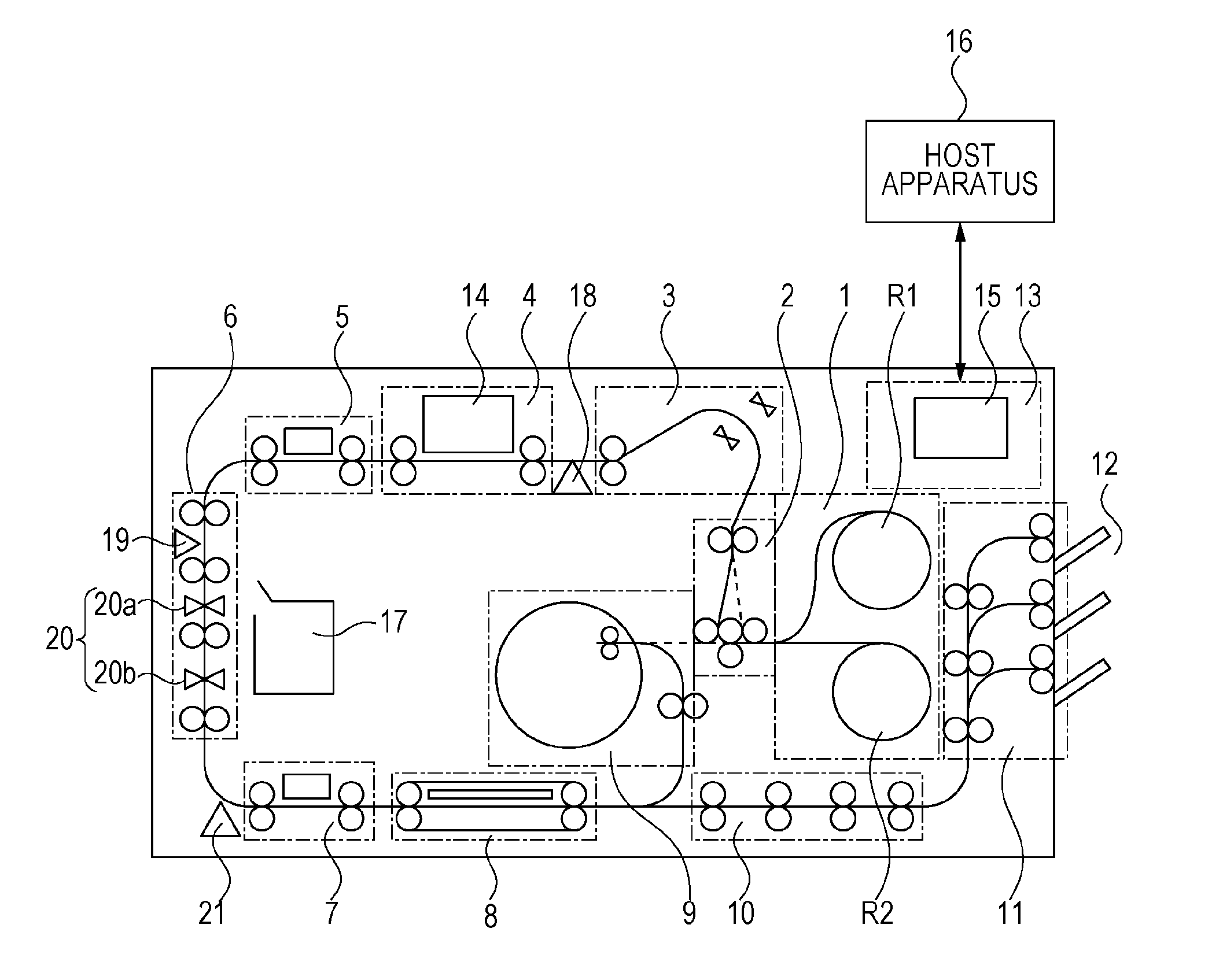
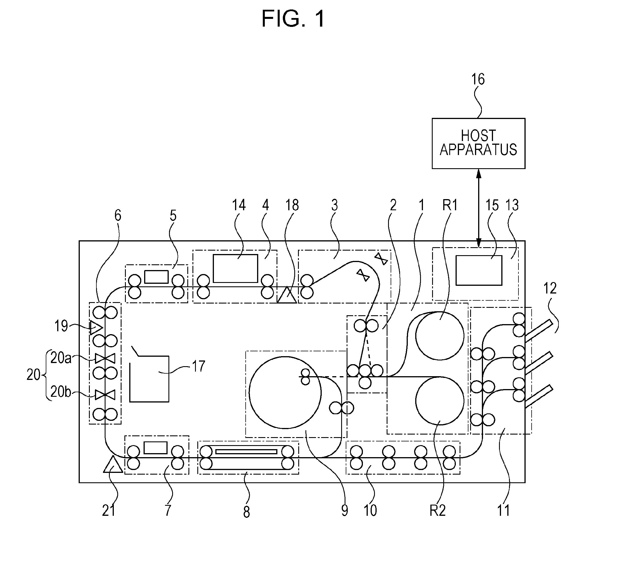
[0025]Hereinafter, a description will be provided of a print apparatus using an inkjet system according to an embodiment. The print apparatus of the present example is a high speed line printer that uses a lengthy continuous sheet (long continuous sheet which is longer than a length of a repetitive print unit in a conveying direction (which is referred to as one page or unit image)) and deals with both a simplex printing and a duplex printing. For example, this is suitable to a field of a large amount of prints in a print laboratory or the like. It is noted that according to the present specification, even when a plurality of small images, characters, and spaces are mixed in an area of one print unit (one page), the components included in the relevant area are collectively referred as one unit image. In other words, the unit image means one print unit (one page) in a case where a plurality of pages are sequentially printed on the continuous sheet. It is noted that this may simply be...


PUM


Abstract

A first reading unit that reads a pattern or an image formed on a sheet by a print unit for recognizing a print unit state, a second reading unit that reads a cut mark formed on the sheet on a downstream thereof, a cutter that cuts the sheet on a downstream thereof, and a reverse unit that reverses the sheet fed to the print unit again are provided. In duplex printing, the sheet where images are sequentially printed on a first surface is led to the reverse unit, the front and rear faces are reversed, and the sheet is fed to the print unit again. The sheet where images and cut marks are sequentially printed on a second surface is cut by the cutter for each piece and discharged. The sheet is cut on the basis of a reading of the cut mark by the second reading unit.

Description

BACKGROUND OF THE INVENTION[0001]1. Field of the Invention[0002]The present invention relates to a print apparatus using a continuous sheet.[0003]2. Description of the Related Art[0004]Japanese Patent Laid-Open No. 2005-305712 discloses a print apparatus that sequentially prints a plurality of images on a continuous sheet. This print apparatus is provided with a density sensor (35) that measures an ink density of an image on a downstream of a print head (H), a cut position sensor (41) on a downstream thereof, and a cutter (40). By using the print head, together with the plurality of images, a cutter mark is recorded in a margin area between adjacent images, and the sheet is cut for each image on the basis of a cut mark detection by the cut mark sensor. The finished print product thus cut for each image is generated.[0005]In a field such as a photograph album binding, a single print apparatus desirably prints on both sides of a continuous sheet at a high speed and with a high quality...

Claims


Application Information

Patent Timeline
Patent Type & Authority Applications(United States)
IPC IPC(8): B41J29/38
CPCB41J3/60B41J29/393B41J13/0045B41J11/663
Inventor TESHIGAWARA, MINORUNAGOSHI, SHIGEYASUMURAYAMA, YOSHIAKIHIROSAWA, SUSUMUMURASE, TAKESHIKANO, YUTAKAAZUMA, SATOSHIMURO, KENTAROUKATO, MASAOKATO, MINAKO
Owner CANON KK
Why Eureka
Try Eureka