Contoured bone plate for fracture fixation having hook members

a bone plate and fracture technology, applied in bone drill guides, medical science, surgery, etc., can solve the problems of small end fragment, difficult use of bone plates, and simply not enough bone in the end fragmen

Active Publication Date: 2011-09-01
TRIMED
View PDF7 Cites 8 Cited by
  • Summary
  • Abstract
  • Description
  • Claims
  • Application Information

AI Technical Summary

Problems solved by technology

Difficulties in using bone plates may arise in certain fractures occurring relatively close to the end of a bone, creating a relatively small end fragment.
In this situation, there may simply be not enough bone available in the end fragment to accommodate a sufficient number of screws to achieve secure fixation.
As a result, a surgeon using a conventional bone plate may use a suboptimal number of screws, which can lead to postoperative failure.
In such situations, only a very small distal fragment may be present, providing inadequate room for more than one or two screws to be placed.
Moreover, since the deep portion of this bone is a part of the overall ankle joint, screws cannot be placed through both cortices, as is commonly practice with plate / screw techniques.
Accordingly, the surgeon may be faced with the undesirable situation of having the patient leave the operating room with only one or two screws engaging a bone surface directly under a bone plate.
However, this terminal bone fragment may still remain far from being well secured.
In addition, this technique does not address the problem of creating holes in the bone at the correct depth for engagement by the hooks, but rather relies on manual pressure on the plate to attempt penetration of the bone by the hooks at whatever level they happen to contact.
As can be noted by the examples in this article, the hooks may fail to penetrate the bone resulting in less than satisfactory engagement and fixation of the terminal fragment by the hooks as well as prominence of the hooks in the soft tissue because of incomplete seating.
Finally, since these implants have hooks that extend an equal distance from the end of the plate, this design does not allow completely seating of both hooks in the common situation in which the bone surface at the terminal end is at an angle to the plane that is perpendicular to the long axis of the bone.

Method used


Image

  • Contoured bone plate for fracture fixation having hook members
  • Contoured bone plate for fracture fixation having hook members
  • Contoured bone plate for fracture fixation having hook members

Examples


Embodiment Construction

[0045]While several different embodiments of the present invention are described herein and shown in the various figures, common reference numerals in the figures denote similar or analogous elements or structure amongst the various embodiments.

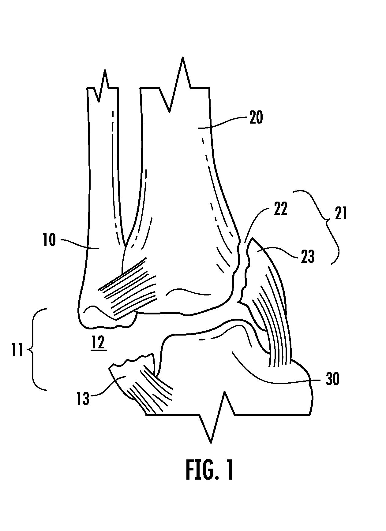
[0046]A simplified anterior view of a portion of the right human ankle is shown in FIG. 1 as comprising fibula 10, tibia 20, and talus 30. Right fibula 10 is shown having a fracture of the lateral malleolus 11 thereof, creating a small terminal fragment 13 proximate fracture site 12. Simultaneously, right tibia 20 is shown having a fracture of the medial malleolus 21 thereof, creating a small terminal fragment 23 proximate fracture site 22.

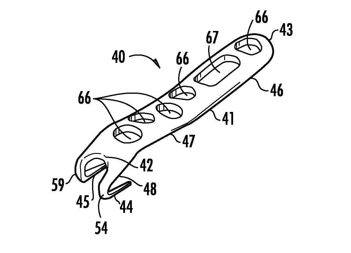
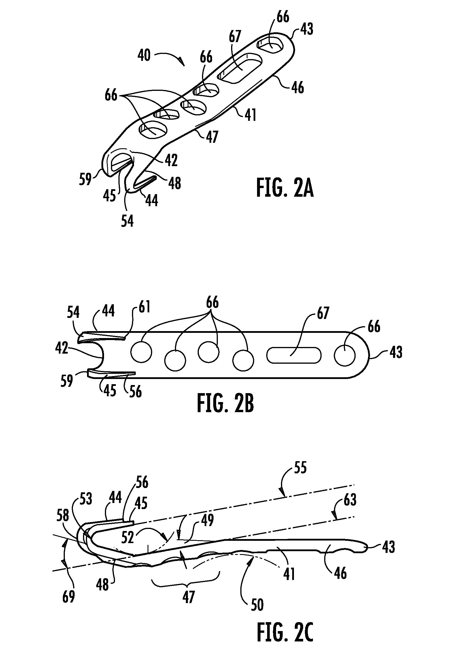
[0047]A six-hole left offset bone plate 40 of the present invention, configured for use in conjunction with fractures of the lateral malleolus, is shown in FIGS. 2A through 2F as comprising an elongated body 41, having a first end 42 proximate first hook member, or tooth member 44 and second hook member, or...


PUM


Abstract

A bone fixation plate for fixation of fractures having a small terminal bone fragment, such as fractures of the lateral malleolus. The bone fixation plate includes an elongated body, and two hook members extending from a first end of the elongated body. Each hook member curves back upon a bottom surface of the elongated body, back towards a second end of the elongated body, and terminating in a pointed prong region. The elongated body includes a first region, a second region, and an angled region disposed between the first and second region. The prong region has a longitudinal axis that is substantially parallel to a longitudinal axis of the angled region of the elongated body of the bone plate.

Description

CROSS-REFERENCE TO RELATED APPLICATIONS[0001]This application is a division of U.S. application Ser. No. 12 / 114,916 filed May 5, 2008, the entirety of which is hereby incorporated by reference.BACKGROUND OF THE INVENTION[0002]1. Field of the Invention[0003]The present invention relates, in general, to the fixation of bone fractures and, more particularly, to the fixation of bone fractures having small fragments proximate a terminal end of a bone.[0004]2. Description of Related Art[0005]Plates and screws are well accepted techniques for fixation of fractures. The standard bone plate is a planar bar of material, usually metal, having circular and / or slotted holes through which bone screws are placed. The bone plate is used to span a fracture and fixation screws are placed through holes in the bone plate positioned on either side of the fracture to secure the bone fragments the plate.[0006]One variation of the standard bone plate is to modify the configuration of the screw holes to hel...

Claims


Application Information

Patent Timeline
Patent Type & Authority Applications(United States)
IPC IPC(8): A61B17/80
CPCA61B17/1728A61B17/1739A61B2017/1775A61B17/809A61B17/8061A61B17/1775
Inventor MEDOFF, ROBERT J.
Owner TRIMED
Why Eureka
Try Eureka