
Touch Panel Apparatus

a technology of touch panel and output pin, which is applied in the direction of instruments, computing, electric digital data processing, etc., to achieve the effect of reducing the amount of electrode output pins and economizing manufacture costs

Inactive Publication Date: 2011-09-08
CHUNGHWA PICTURE TUBES LTD
View PDF3 Cites 14 Cited by
  • Summary
  • Abstract
  • Description
  • Claims
  • Application Information

AI Technical Summary

Benefits of technology

[0007]It is therefore an object of the invention to share the output pins of electrode for reducing the amount of the electrode output pins and economizing manufacture cost.
[0008]Another object of the invention is to reduce the computing data amount of the MCU and the responding time of the MCU, it should enhance the responding speed of the touch panel and increase the accuracy of the estimation of the position. The present invention provides a responsive touch panel to enhance processing efficiency.
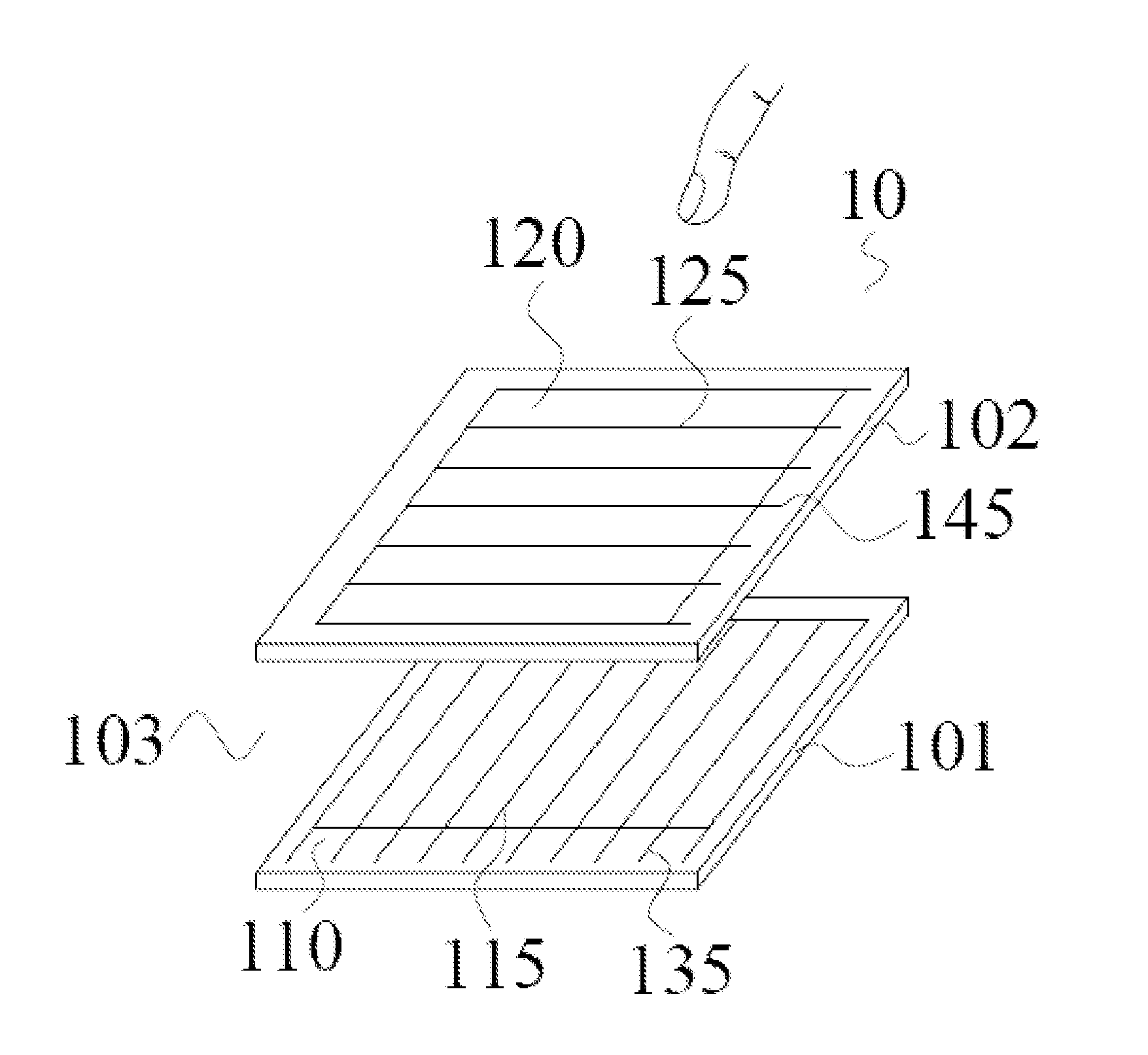
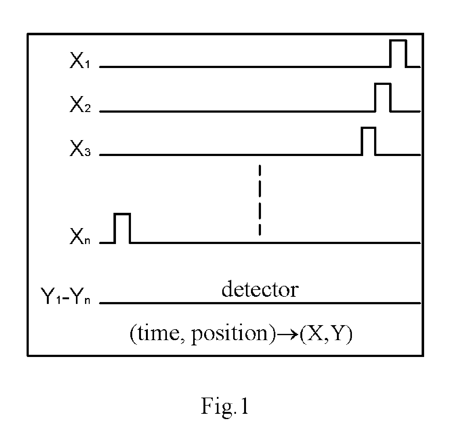
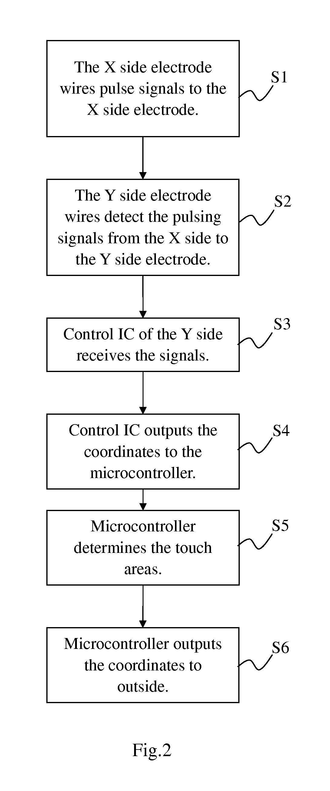
[0011]The present invention discloses a method for transmitting signals to control IC by grouping the Y side electrode wires into every three or more than three wires as a unit and an electrode wire is selected from each group. Then, an electrode wire of the one of the groups and an electrode wire of another group are coupled jointly to the one of the second axis pins, and the signals are transmitted to the control IC. In other words, electrode wires selected from every electrode wire groups are coupled with the same output pin. When the output signals transmit to the control IC, the output signals would be transmitted via the pin and the control IC would interpret and determine the several of arrangement and combination to represent the signal by logic computing method. Because of the present invention utilizes the arrangement and combination of the electrode output pins and logic computing method to increase the transmittable area of each pin, and instead of the conventional pin which only transmits the signals from single area to control IC. Therefore, the present invention can reduce the amount of the electrode output pins efficiently and the computing data amount of the MCU is reduced accordingly.
[0012]One of the merits of the present invention is to save the amount of the electrode output pins and economize the manufacture cost.
[0013]Another merit of the present invention is to reduce the computing data amount of the control IC and enhance the responding speed of the touch panel.
[0014]Further merit of the present invention is collocated with application, such as the size of the products, and increases the efficiency of the touch panel by logic computing method.

Problems solved by technology

However, the relevant industries attach importance to application of the matrix resistive touch panel gradually, because of the lower price and cost.

Method used


Image

  • Touch Panel Apparatus
  • Touch Panel Apparatus
  • Touch Panel Apparatus

Examples


Embodiment Construction

[0025]The invention hereinafter will be described in greater detail with preferred embodiments of the invention and accompanying illustrations. Nevertheless, it should be recognized that the preferred embodiments of the invention are not provided to limit the invention but to illustrate it. The present invention can be practiced not only in the preferred embodiments herein mentioned, but also in a wide range of other embodiments besides those explicitly described. Further, the scope of the present invention is expressly not limited to any particular embodiments except what is specified in the appended claims.

[0026]The present invention provides a touch panel apparatus with shared output pins configuration of vertical electrodes, and more particularly to a matrix resistive touch panel which can reduce the computing data amount of the control IC to enhance the responding speed of the touch panel.

[0027]With reference to FIG. 4, a diagram of the system of the touch panel apparatus with ...


PUM


Abstract

The present invention discloses a touch panel apparatus with shared output pin configuration and method thereof. The method to reduce output pin is to group the electrode lines on the substrate into at least one unit, and each unit includes plural lines. At least one of the second axial electrode line of the electrode line group and at least one of the second axial electrode line of the another electrode line group couple to plural the second axial pins. Then, the vertical electrodes deliver the signals to the control IC through the pin coupled with the control IC. The control IC sends the output signals to the micro controller unit and the micro controller unit utilizes logical operators to estimate the coordinate position of touch point.

Description

FIELD OF THE INVENTION[0001]The present invention relates to a touch panel apparatus, and more particularly to a touch panel apparatus with shared output pins configuration of vertical electrodes.BACKGROUND OF THE INVENTION[0002]With rapid developments and applications of the technology, the input devices of the information, communications and electronics products and other related devices tend to diversify. Because of the humanity input interface, touch panel has become an essential means for human life. User is free of teaching and can use through an intuitive and direct touching.[0003]The principle of the touch panel technology is that when user's fingers or other media touch on the touch panel screen, the coordinates of the touch points are detected by different induction types, e.g. voltage, current, sound wave or infrared. The touch panel can be divided into various categories according to different driving modes of the touch panel, for example, a resistive panel, a capacitive...

Claims


Application Information

Patent Timeline
IPC IPC(8): G06F3/041
CPCG06F3/041G06F3/0446G06F3/04164G06F3/0443G06F3/0445
Inventor CHOU, PIN-HUNGLI, YU HUNG
Owner CHUNGHWA PICTURE TUBES LTD
Learn More