Fastener system with stable engagement and stick fit

a technology of stable engagement and fastener, which is applied in the direction of threaded fasteners, screwing, manufacturing tools, etc., can solve the problems of high localized stress, difficult design considerations, and limited contact between the driver and the recess surface, and achieves a wide area contact rarely achieved, if any, and avoids premature interference between the bit and the recess. , the effect of enhancing engagemen

Active Publication Date: 2011-09-08
PHILLIPS SCREW
View PDF36 Cites 37 Cited by
  • Summary
  • Abstract
  • Description
  • Claims
  • Application Information

AI Technical Summary

Benefits of technology

Various embodiments described herein provide a fastener system having straight walled driving surfaces that provides a reliable stick fit feature, while also improving stability of engagement between the system components. An important feature of the new system is to allow engagement of existing standard straight walled drivers in the new system. In order to accomplish this goal, a new driver and recess system is constructed as described below.
In this manner, stick fit is provided, while stability of the engagement of driver and recess is enhanced. In addition, by enlarging the dimensions slightly, relative to a standard recess of a straight walled fastener system, the use of a standard driver is allowed. However, as indicated above there will be no stick fit engagement, when using a standard driver.

Problems solved by technology

Such conditions present difficult design considerations, particularly with respect to the drive systems and, more particularly, with threaded fasteners having a driver engageable recess in the fastener head or a driver engageable exterior contour to the fastener head.
In all of these systems, the practical result of the necessity for such clearance is that substantial face-to-face, broad area contact between the driver and recess surfaces is seldom achieved, if at all.
Consequently, when torque is applied by the driver, the forces applied to the screw head tend to be concentrated in localized areas with resulting high localized stresses and unstable axial alignment.
Such localized high stress can plastically deform the recess, forming ramps or other deformations that result in premature, unintended disengagement of the driver from the recess.
Although straight walled fasteners are in successful general use in many applications, they may experience difficulties resulting from axially misalignment between driver and fastener.
In addition it has been difficult to obtain a reliable friction engagement that provides a stick fit feature.
It is observed that the configuration results in a line contact between driver and recess both circumferentially and axially and will not enhance stability or frictional engagement.
This is because there is a reluctance to alter the recess geometry as it would result in a loss of compatibility with existing drivers.

Method used


Image

  • Fastener system with stable engagement and stick fit
  • Fastener system with stable engagement and stick fit
  • Fastener system with stable engagement and stick fit

Examples


Embodiment Construction

Although the present invention will be described with reference to the embodiments shown in the drawings, it should be understood that the present invention may have alternate forms. In addition, any suitable size, shape or type of elements or materials could be used.

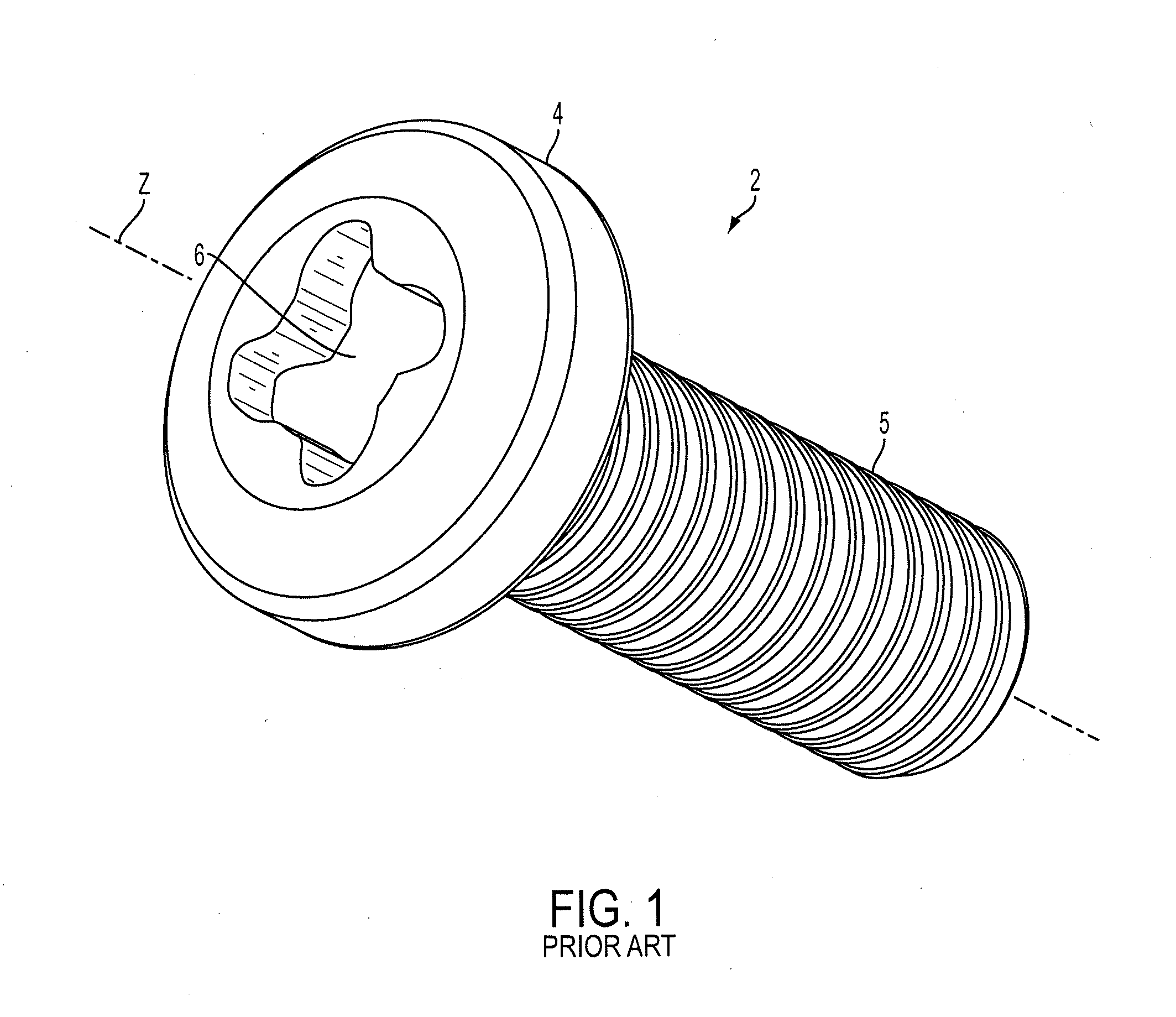
FIG. 1 illustrates an example of a threaded fastener having straight walled drive surfaces of the prior art. The term “straight walled drive surfaces” is used herein to refer to fastener systems in which the driving surfaces are substantially in alignment, i.e. parallel with the longitudinal axis of the fastener. It is accepted in the fastener industry that statements, such as “parallel alignment” are subject to some deviation tolerances, as it is understood that such alignment is subject to manufacturing tolerances and may vary slightly in actual practice. In particular, FIG. 1 illustrates fasteners as described in the published application to Dilling referenced above. In general, fastener systems of this type are cons...


PUM

PropertyMeasurementUnit
anglesaaaaaaaaaa
anglesaaaaaaaaaa
angleaaaaaaaaaa

Abstract

Various embodiments described herein provide a fastener system having straight walled driving surfaces that provides a reliable stick fit feature, while also improving stability of engagement between the system components. A feature of the new system is to allow engagement of existing standard straight walled drivers in the new system.

Description

BACKGROUNDThis application relates in general to drive systems for threaded fasteners, tools for their manufacture, and drivers for applying torque to such fasteners. More specifically this application relates to fasteners that are constructed with straight walled recesses. In particular a fastener system is constructed wherein the driver and fastener engage with improved stability of axial alignment and stick fit.Threaded fasteners commonly used in industrial applications typically are driven by power tools at high speeds and under high torque loads. Such conditions present difficult design considerations, particularly with respect to the drive systems and, more particularly, with threaded fasteners having a driver engageable recess in the fastener head or a driver engageable exterior contour to the fastener head. Ideally, such a drive system needs to be easily manufactured, both as to recess and head geometry, as well as to associated tooling for forming the fastener head and the ...

Claims


Application Information

Patent Timeline
Patent Type & Authority Applications(United States)
IPC IPC(8): F16B23/00B21H3/02B21K1/44
CPCB25B15/005F16B23/003B23P15/00B25B13/065F16B23/0038B25B23/00B25B23/02
Inventor HUGHES, BARRY J.DILLING, GARY
Owner PHILLIPS SCREW
Why Eureka
Try Eureka