

Golf club head
a club head and golf technology, applied in the field of golf club heads, can solve the problems of simple manufacturing limited to the inherent material properties of one material, and the use of homogeneous and non-homogeneous face materials, etc., to achieve the effect of increasing the robustness of the ball speed
- Summary
- Abstract
- Description
- Claims
- Application Information
AI Technical Summary
Benefits of technology
Problems solved by technology
Method used
Image

Examples
second embodiment
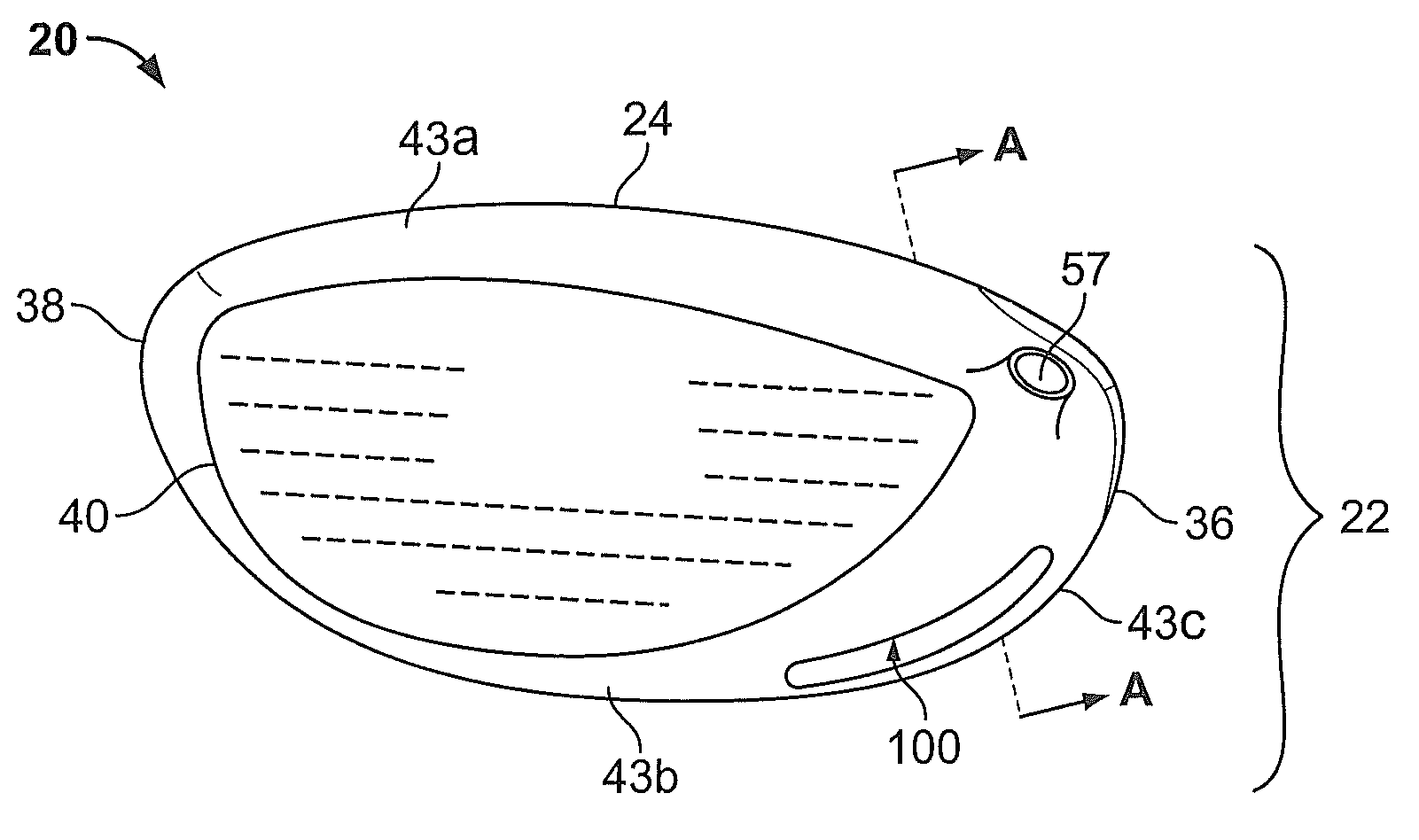
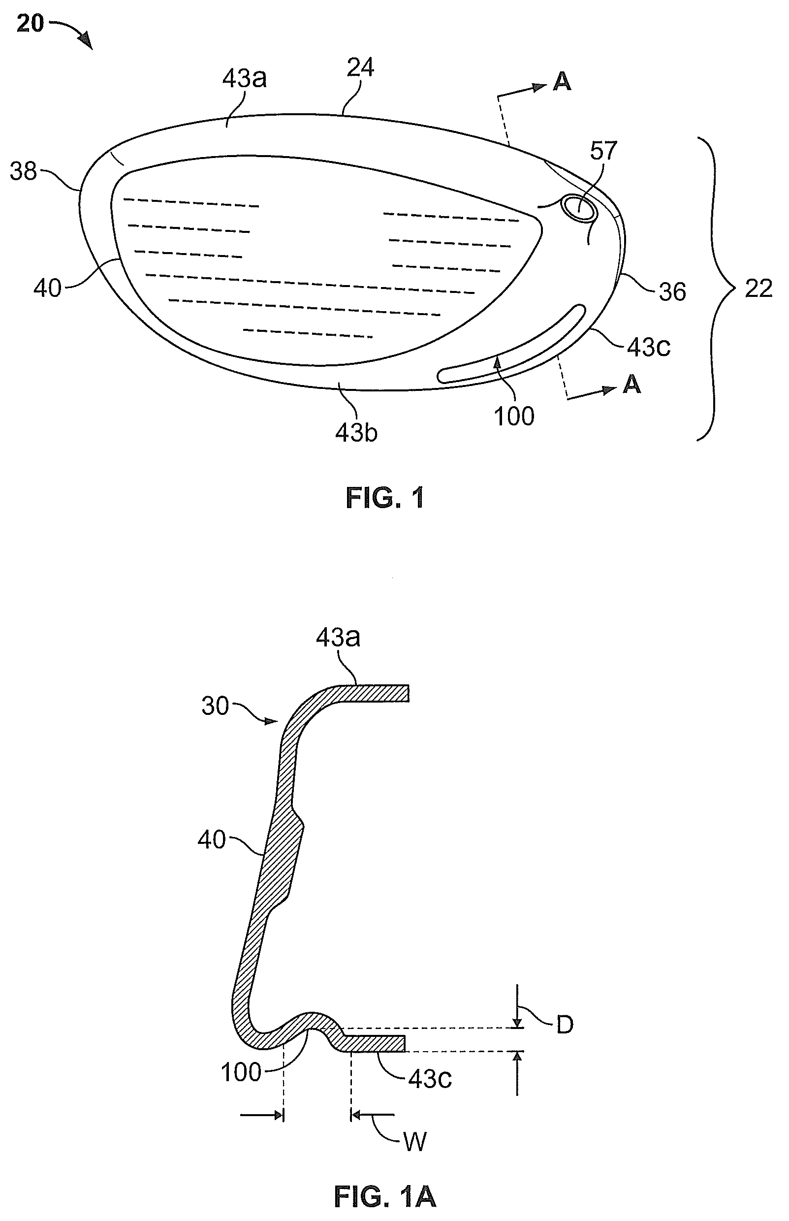
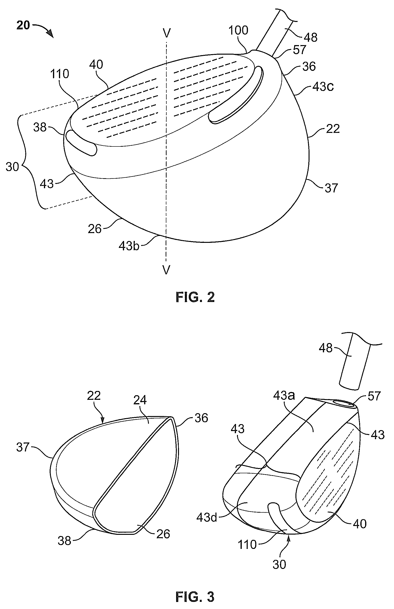
[0034]the golf club head 20 of the invention is shown in FIG. 4. In this embodiment, the golf club head 20 has a body 22 comprising a crown 24, a sole 26 (not shown), a back portion 37, a heel end 36, a toe end 38, a hosel 57 to which a shaft 48 (not shown) may be attached, and a recessed portion 33 which, together with the crown 24, sole, 26, heel end, 36, and toe end 38, defines an opening 32 for receiving a face portion. In this embodiment, the face portion is a striking face 40 insert that is attached to the body 22 over the opening 32 defined by the recessed portion 33 and the other elements of the body 22.
[0035]In this second embodiment, a first channel 100 is defined in the heel end 36 and a second channel 110 (not shown) is defined in the toe end 38, as described above in relation to the first embodiment of the invention. The first channel 100 and second channel 110 extend along the heel end 36 and toe end 38, respectively, proximate to and parallel with the striking face in...
first embodiment
[0037]The locations of the first channel 100 and second channel 110 also may vary. For example, as described above in reference to the invention, the first channel 100 and second channel 110 are located closer to the sole 26 than the crown 24. In another embodiment, the first channel 100 and the second channel 110 may be located closer to the crown 24 than the sole 26. The first channel 100 and second channel 110 may also be located in substantially mirror imaged positions with respect to a vertical plane bisecting the striking face insert 40. In an alternative embodiment, the golf club head 20 may comprise only the first channel 100 or the second channel 110 as described herein.
[0038]A third embodiment of the golf club head 20 of the invention is shown in FIG. 5. In this embodiment, the golf club head 20 has a body 22 comprising a crown 24, a sole 26 (not shown), a back portion 37 (not shown), a heel end 36, a toe end 38, a hosel 57 to which a shaft 48 (not shown) may be attached, ...
fourth embodiment
[0041]the golf club head 20 of the invention is shown in FIG. 6. In this embodiment, the golf club head 20 has a body 22 comprising a crown 24, a sole 26 (not shown), a back portion 37 (not shown), a heel end 36, a toe end 38, a hosel 57 to which a shaft 48 (not shown) may be attached, and an opening 32 (not shown) defined by the crown 24, sole, 26, heel end, 36, and toe end 38, for receiving a striking face insert 40. The striking face insert 40 is attached to the body 22 over the opening 32 defined by the other elements of the body 22. This embodiment further comprises two continuous channels 120 defined on the crown 24, sole 26, heel end 36, and toe end 38. In this embodiment, the two channels 120 extend proximate to the striking face insert 40 and substantially encircle the striking face insert. The channels are approximately 0.090 to 0.250 inch deep (“D”), 0.12 to 0.375 inch wide (“W”), and are spaced apart from one another by 0.06 to 0.50 inch (“S”). In a most preferred embodi...
PUM
 Abstract
Description
Claims
Application Information