
Surface cleaning apparatus

a technology for cleaning apparatuses and surfaces, which is applied in the direction of suction cleaners, cleaning filter means, domestic applications, etc., can solve the problems of increasing the hand weight of the unit and the blockage of the filter with use, and achieves the effect of reducing the suction provided by the unit, enhancing the surface area, and reducing the hand weigh

Active Publication Date: 2011-09-15
OMACHRON INTPROP
View PDF7 Cites 80 Cited by
  • Summary
  • Abstract
  • Description
  • Claims
  • Application Information

AI Technical Summary

Benefits of technology

[0005]According to one aspect, a hand carriable surface cleaning apparatus is provided wherein the size, configuration and / or positioning of the dirt collection chamber may be varied so as to enable the dirt collection capacity of the unit to be increased without undesirably increasing the size of the unit or the size of the unit may be decreased without undesirably reducing the dirt collection capacity of the unit.
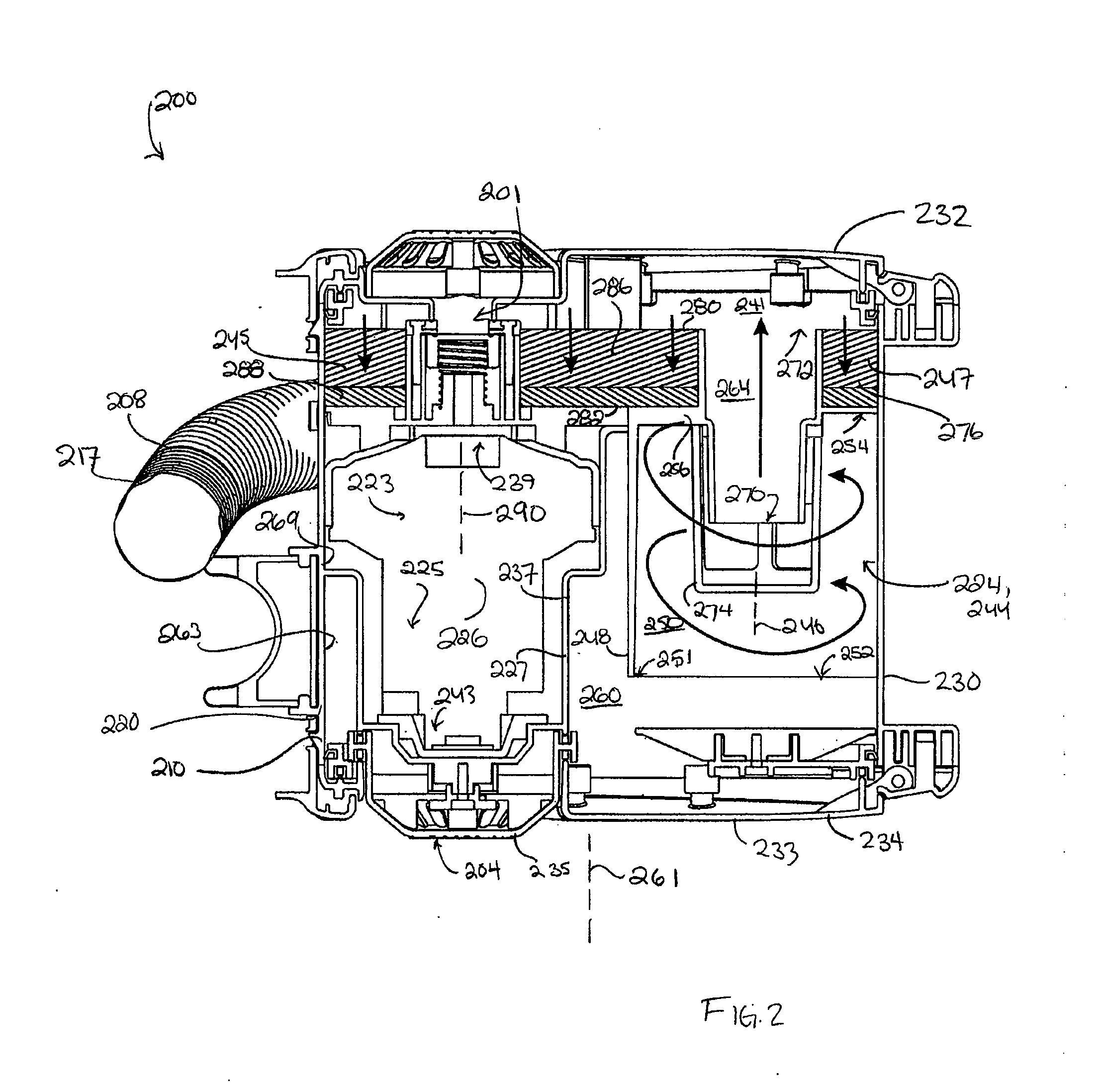
[0035]For example, a suction motor may be positioned beside a cyclone and extend in the same direction of the cyclone. Accordingly, one end of a cyclone may be adjacent the inlet end of the suction motor (e.g., positioned in about the same plane). The pre-motor filter (preferably a foam filter and more preferably a foam filter with a felt filter downstream thereof) may be configured to overlie part or all of the cyclone. Alternately, or in addition, the pre-motor filter may overlie part of the open volume between the suction motor and the cyclone. If the dirt collection chamber is positioned to occupy some of the open volume, then the pre-motor filter may alternately or in addition overlie part or all of the dirt collection chamber. Accordingly, a pre-motor filter with an enhanced surface area of the upstream side may be provided without substantially increasing the size of the unit.

Problems solved by technology

However, that would increase the hand weight of the unit.
However, the filter will become clogged with use.

Method used


Image

  • Surface cleaning apparatus
  • Surface cleaning apparatus
  • Surface cleaning apparatus

Examples


Embodiment Construction

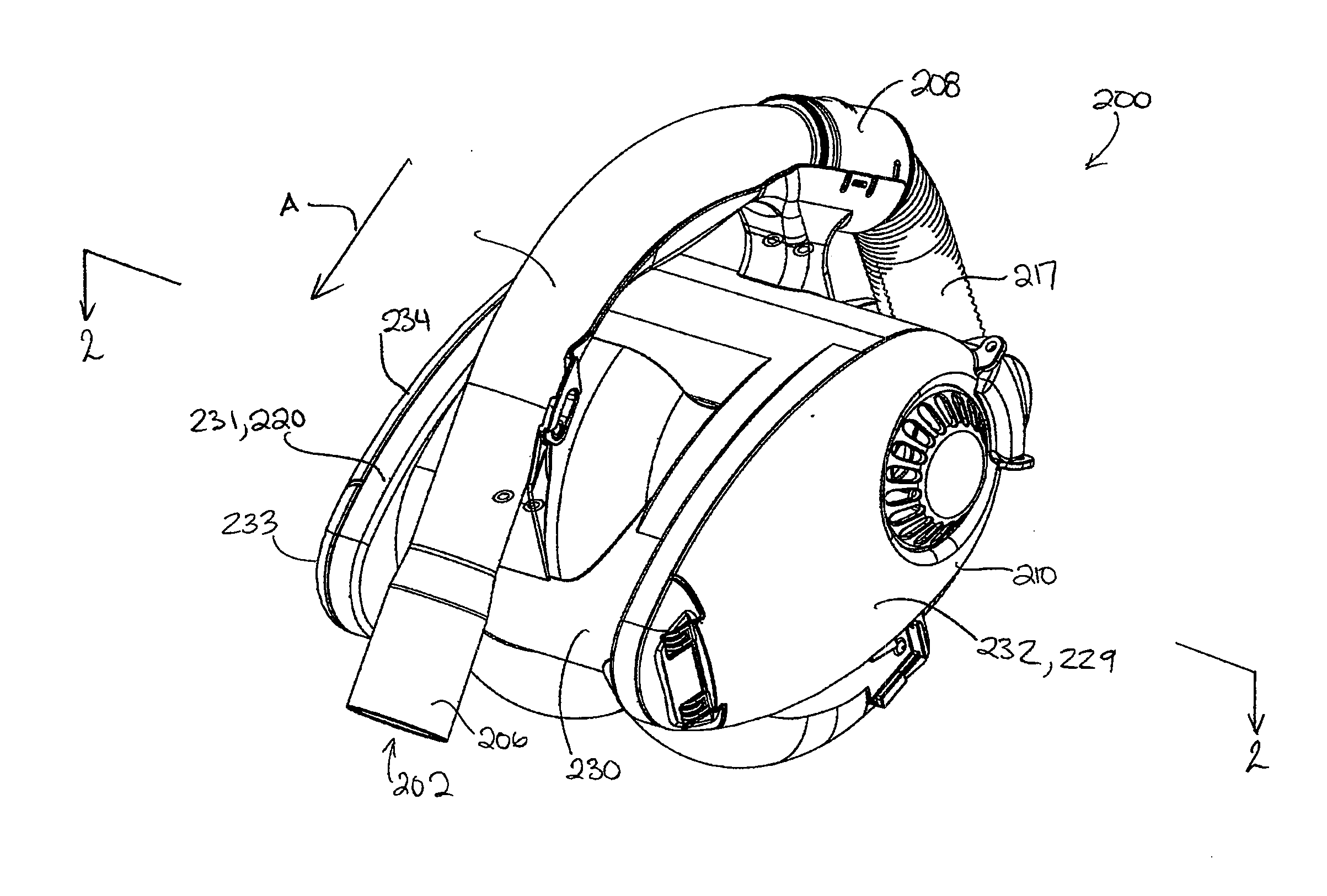
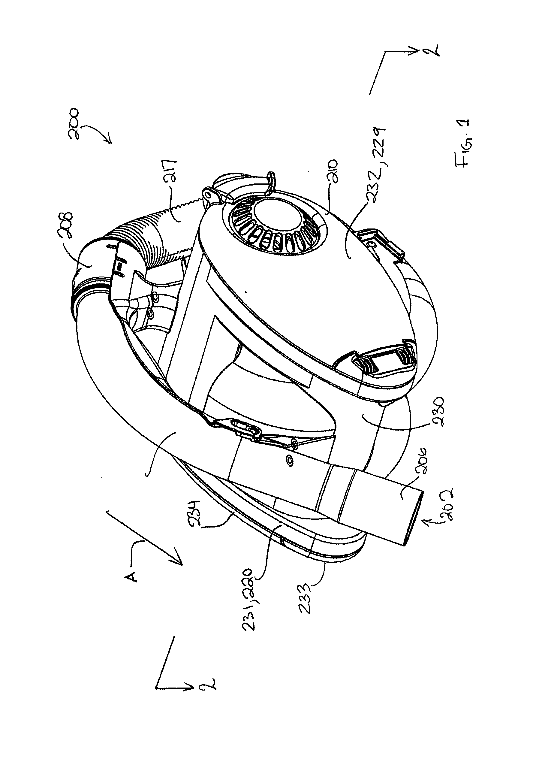
[0056]Referring to FIG. 1, an embodiment of a surface cleaning apparatus200 is shown. In this embodiment the surface cleaning apparatus 200 is a hand operable surface cleaning apparatus. The surface cleaning apparatus 200 is usable in a forward direction of motion, indicated by arrow A in FIG. 1.

[0057]Referring to FIG. 2, the surface cleaning apparatus 200 has a dirty air inlet 202, a clean air outlet 204 (shown in FIG. 2), and an air flow passage extending therebetween. In the embodiment shown, the dirty air inlet 202 is provided in a nozzle 206. From the dirty air inlet 202, the airflow passage extends through the nozzle 206, and through an air conduit 208, to a suction and filtration unit 210. The clean air outlet 204 is provided in the suction and filtration unit 110. In the embodiment shown, the air conduit 108 includes a wand 214, and a hose 217.

[0058]Referring now to FIGS. 1 and 2, the suction and filtration unit 210 includes a main housing 220. A filtration member 224 is pro...


PUM


Abstract

A surface cleaning apparatus comprises an air flow passage extending from a dirty air inlet to a clean air outlet. A suction motor is positioned in the air flow path. At least one cyclone is positioned in the air flow passage. An associated dirt collection chamber is exterior to the cyclone. The cyclone and the suction motor are positioned side by side and have generally parallel longitudinal axes. The dirt collection chamber may surround part of the suction motor. Alternately, or in addition, a pre-motor filter having an enhanced surface area may be provided by configuring the pre-motor filter to extend outwardly of the pre-motor filter, such as by overlie part of the cyclone or the dirt collection chamber.

Description

FIELD[0001]The disclosure relates to surface cleaning apparatuses, such as vacuum cleaners. Particularly, the disclosure relates hand operable surface cleaning apparatuses.INTRODUCTION[0002]The following is not an admission that anything discussed below is prior art or part of the common general knowledge of persons skilled in the art.[0003]Various constructions for surface cleaning apparatus such as vacuum cleaners are known. Currently, many surface cleaning apparatus are constructed using at least one cyclonic cleaning stage. The air is drawn into the vacuum cleaner through a dirty air inlet and conveyed to a cyclone inlet. The rotation of the air in the cyclone results in some of the particulate matter in the airflow stream being disentrained from the airflow stream. This material is then collected in a dirt collection chamber, which may be at the bottom of the cyclone or in a dirt collection chamber exterior to the cyclone chamber (see for example WO2009 / 026709 and U.S. Pat. No....

Claims


Application Information

Patent Timeline
IPC IPC(8): A47L5/24A47L9/16
CPCA47L9/22A47L9/1683
Inventor CONRAD, WAYNE ERNEST
Owner OMACHRON INTPROP
Learn More