Welding device with integral user interface

a welding device and user interface technology, applied in the field of welding systems, can solve the problems of reducing productivity and the location in which welding operations are performed, and achieve the effect of reducing the number of welding operations

Inactive Publication Date: 2011-09-15
ILLINOIS TOOL WORKS INC
View PDF24 Cites 125 Cited by
  • Summary
  • Abstract
  • Description
  • Claims
  • Application Information

AI Technical Summary

Problems solved by technology

However, the location in which the welding operation is performed may not be proximate to the welding power supply or the wire feeder, for example, in complex welding environments.
Such a feature of traditional systems may decrease productivity by necessitating stoppages in the welding operation.

Method used


Image

  • Welding device with integral user interface
  • Welding device with integral user interface
  • Welding device with integral user interface

Examples


Embodiment Construction

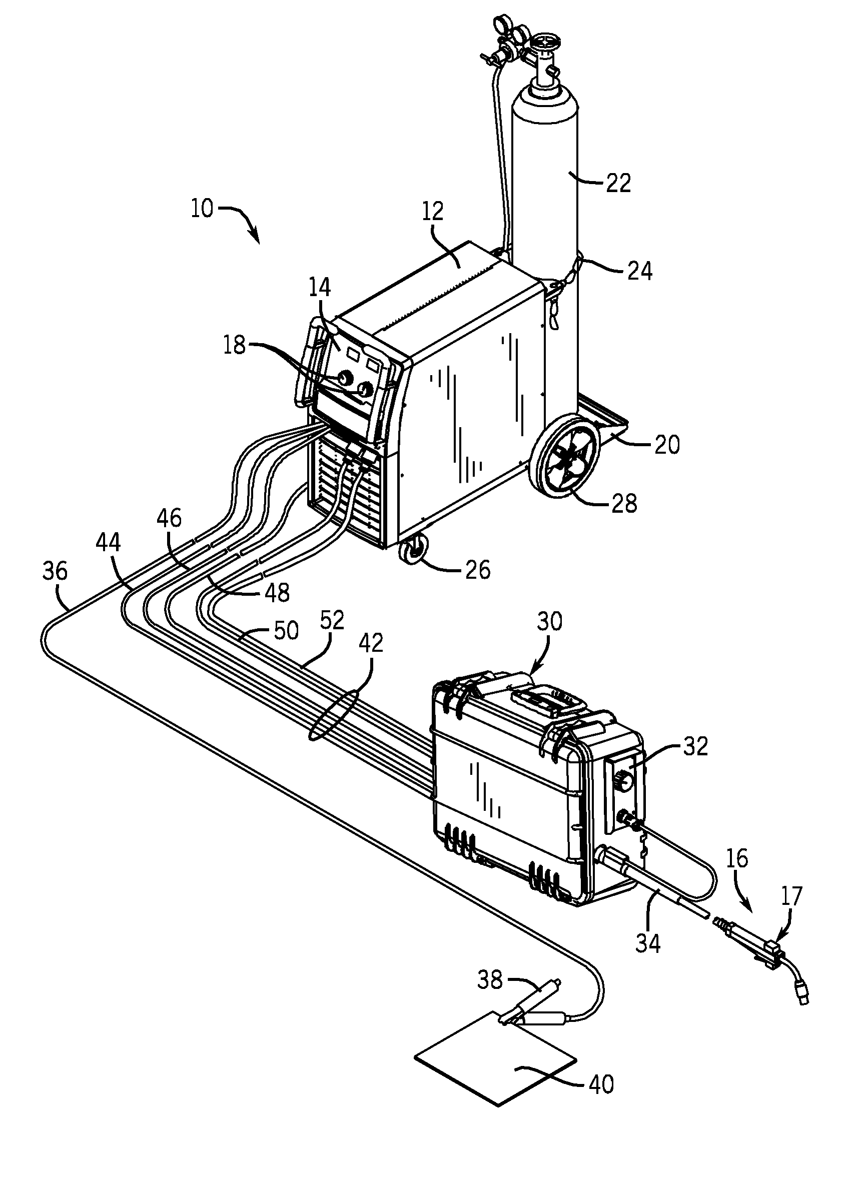
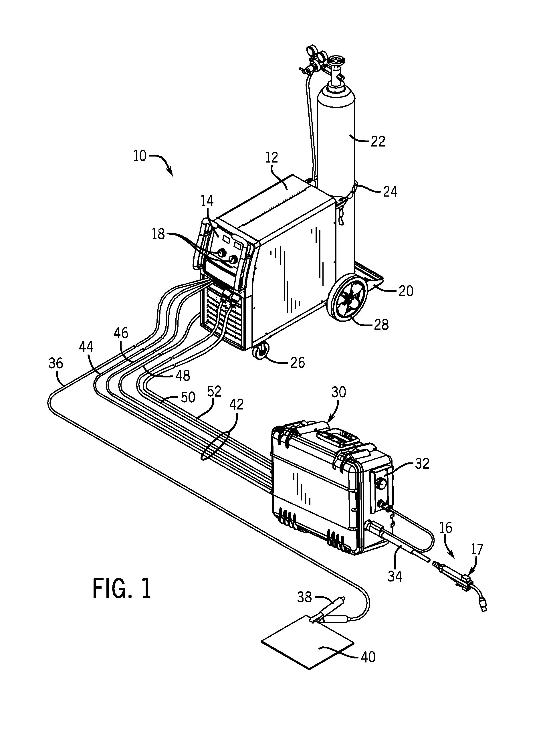
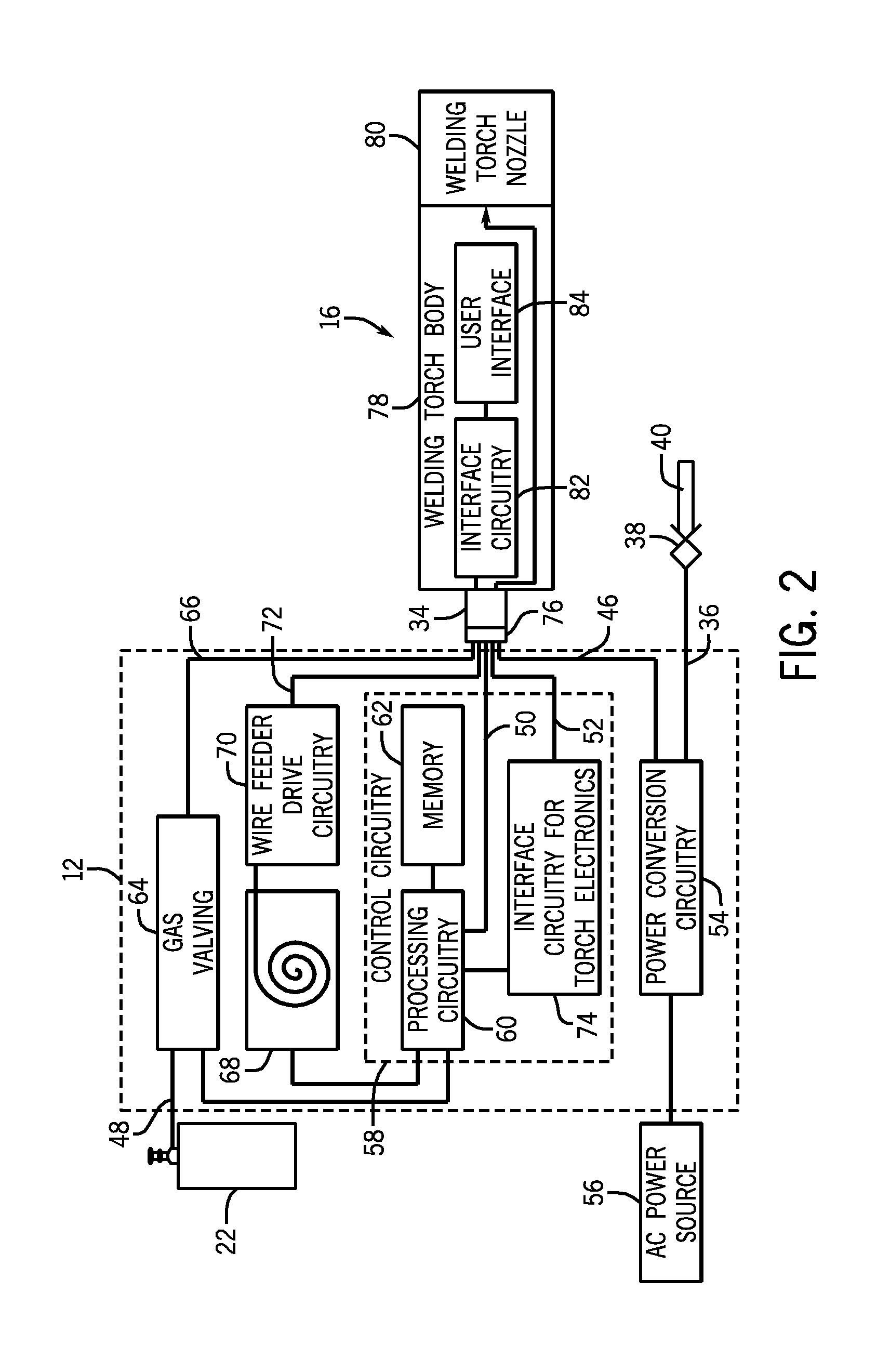
[0015]As described in detail below, embodiments of welding torch assemblies including an integrally formed user interface module are provided. That is, in some embodiments, the user interface module may be integrated into the welding torch assemblies such that the interface module is necessary or essential for completeness of the welding torch assembly. In other words, certain embodiments of the welding torch assemblies may not be capable of functioning for use in a welding environment without the user interface module disposed therein. As such, in some embodiments, the user interface module may be configured for removal from the welding torch assembly, for example, for replacement or repair. However, in such embodiments, while the welding torch assembly is operational in a welding operation, the user interface module is integral with the assembly.

[0016]Further, in some embodiments, the welding torch assembly may also include a lead assembly integrally formed to include one or more ...


PUM

PropertyMeasurementUnit
poweraaaaaaaaaa
timeaaaaaaaaaa
weld poweraaaaaaaaaa

Abstract

Welding torch assemblies including a torch body having a user interface module integrally formed therewith, a welding nozzle, and a torch lead assembly are provided. The user interface module may enable a user to control one or more parameters of a welding operation. The welding nozzle may be coupled to a first end of the torch body. The torch lead assembly may be coupled to a second end of the torch body opposite the first end and may include a weld power lead and a weld control lead.

Description

CROSS REFERENCE TO RELATED APPLICATIONS[0001]This application is a Non-Provisional Patent Application of U.S. Provisional Patent Application No. 61 / 312,533, entitled “Remote User Interface”, filed Mar. 10, 2010, which is herein incorporated by reference.BACKGROUND[0002]The invention relates generally to welding systems, and, more particularly, to welding devices with integral user interfaces for use in welding systems.[0003]Welding is a process that has become increasingly ubiquitous in various industries and applications. While such processes may be automated in certain contexts, a large number of applications continue to exist for manual welding operations. Such welding operations rely on a variety of types of equipment to ensure the supply of welding consumables (e.g., wire feed, shielding gas, etc.) is provided to the weld in an appropriate amount at the desired time. For example, metal inert gas (MIG) welding typically relies on a wire feeder to ensure a proper wire feed reache...

Claims


Application Information

Patent Timeline
Patent Type & Authority Applications(United States)
IPC IPC(8): B23K9/10B23K9/16
CPCB23K9/291
Inventor MEHN, PETER DONALDWELLS, JEFFREY G.HAVEN, CALEB
Owner ILLINOIS TOOL WORKS INC
Why Eureka
Try Eureka