Current sensor

Active Publication Date: 2011-09-15
ALPS ALPINE CO LTD
View PDF2 Cites 45 Cited by
  • Summary
  • Abstract
  • Description
  • Claims
  • Application Information

AI Technical Summary

Benefits of technology

[0018]According to the current sensor of the above embodiment of the invention, since the current sensor includes magnetic sensors disposed on a conductor having at least two separated current-carrying areas with different current magnitudes and detecting a magnetic field generated according to currents flowing through the conductor and a contro

Problems solved by technology

However, since the current sensor in the JP-A 2004-132790 has a wide measuring range, the distance from the conductor needs to be increased, and as a result, a large space is required.
Moreover, if the magnetic sensors are far away from the conductor, it is difficu

Method used


Image

  • Current sensor
  • Current sensor
  • Current sensor

Examples


embodiment 1

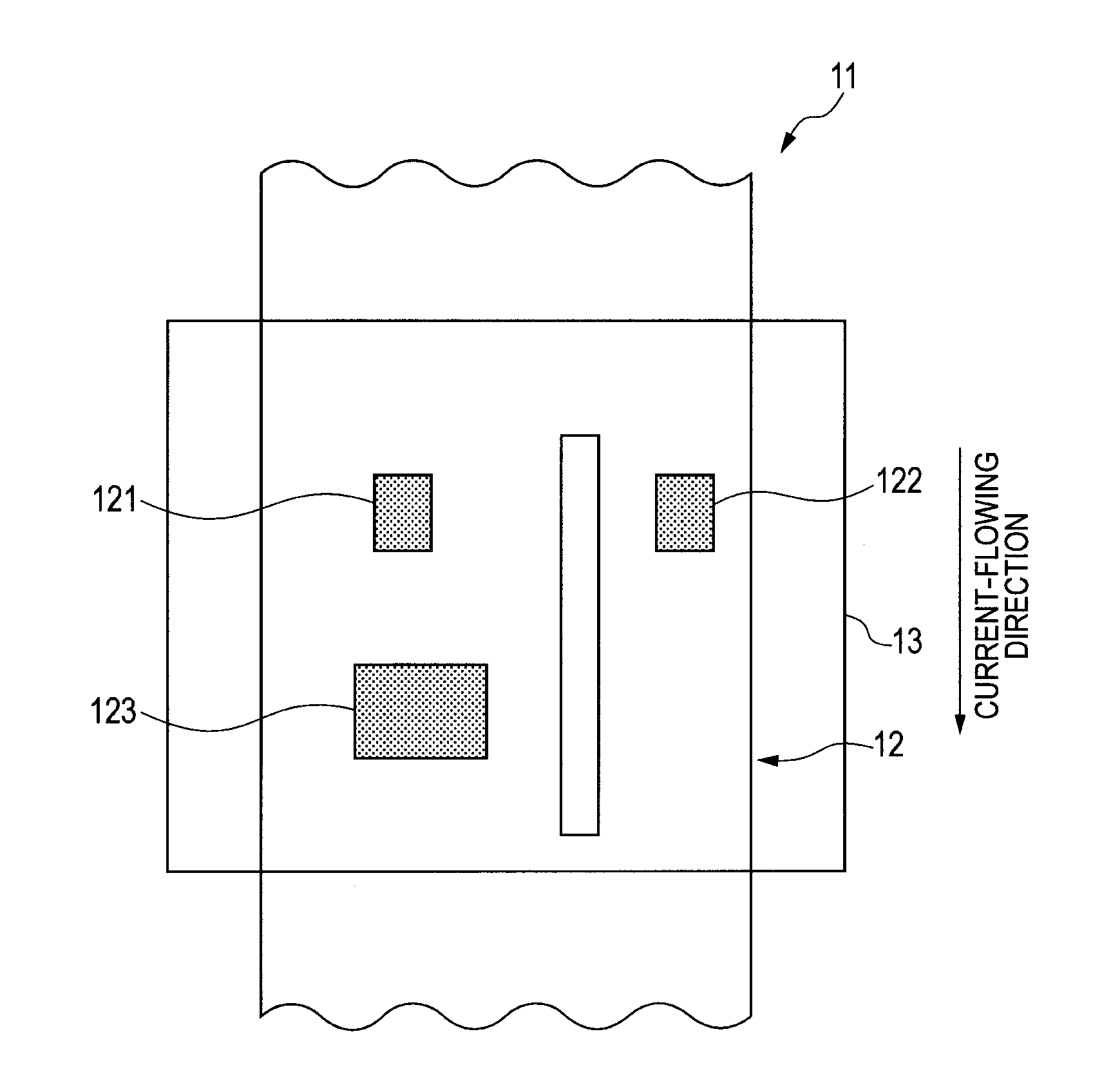
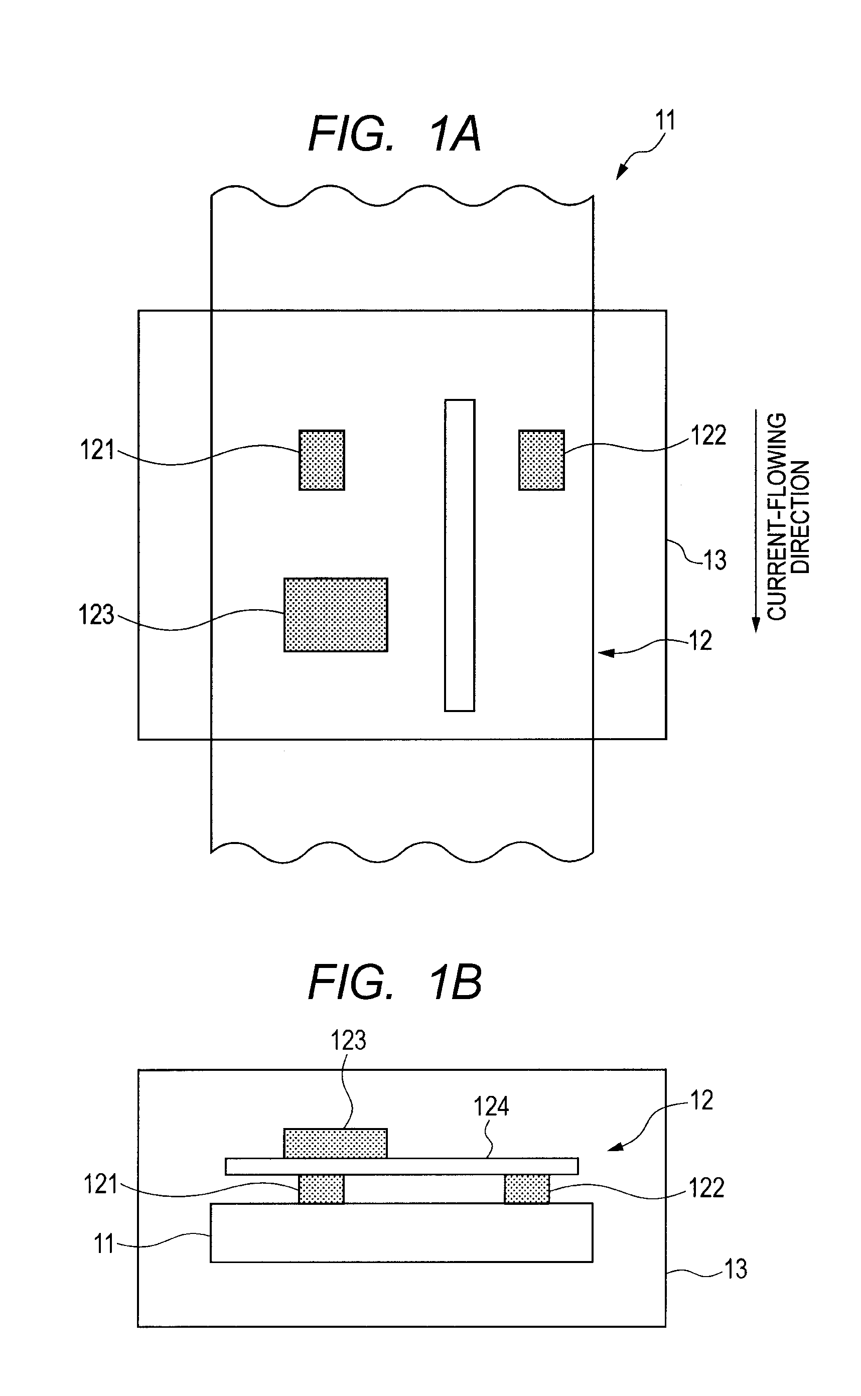
[0033]FIG. 1 is a view showing a current sensor according to Embodiment 1 of the invention. FIG. 1A is an internal perspective plan view, and FIG. 1B is an internal perspective lateral view.

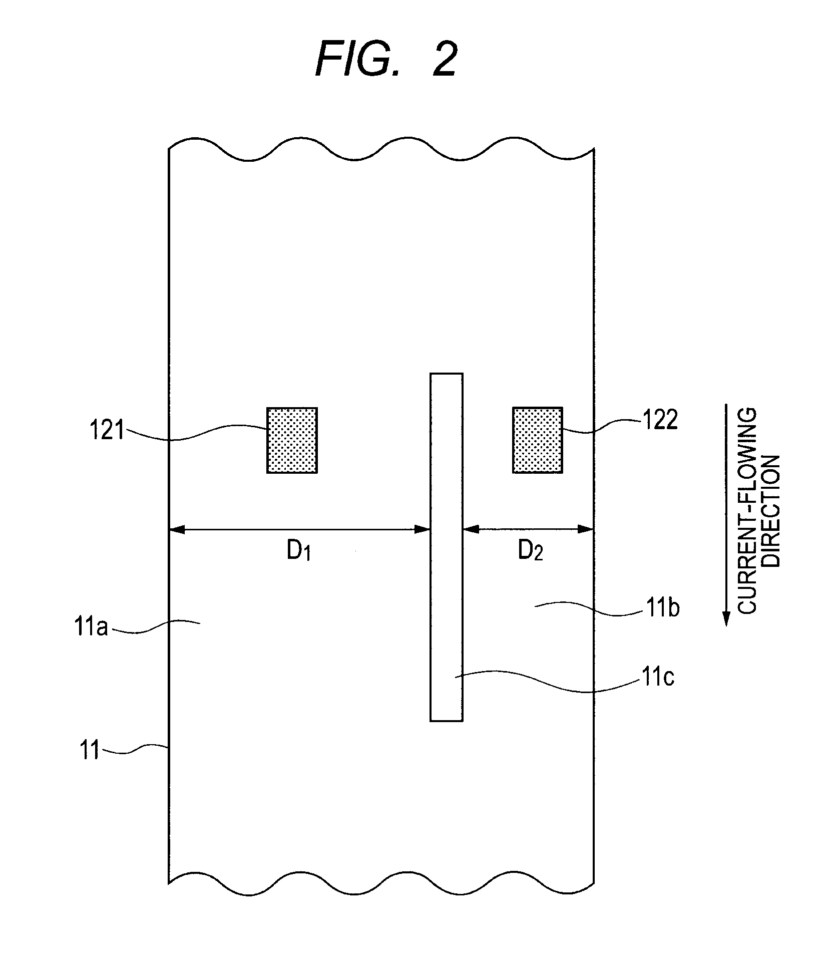
[0034]As shown in FIG. 1A, near a conductor 11 as a current line through which currents flow, a current sensor 12 is disposed. The conductor 11 has at least two separated current-carrying areas with different current magnitudes as shown in FIG. 1A. Herein, as shown in FIG. 2, the conductor 11 is provided with a slit 11 and includes an area 11a having a wide conductor width (length in an orthogonal direction to a current-carrying direction) D1 and an area 11b having a narrow conductor width D2. The current sensor 12 is disposed such that a first magnetic sensor 121 is positioned on the area 11a of the conductor 11 and a second magnetic sensor 122 is positioned on the area 11b of the conductor 11. The current sensor 12 is electrically connected to a first magnetic sensor 121 disposed on the area 11...

embodiment 2

[0051]FIG. 8 is a view illustrating disposition positions of magnetic sensors in a current sensor according to Embodiment 2 of the invention. FIG. 8A is a plan view, and FIG. 8B is a lateral view. In FIG. 8, portions the same as those in FIG. 2 are given the same signs to omit detailed descriptions.

[0052]In the current sensor shown in FIG. 8, in outer positions of the conductor 11, the positions being symmetrical with respect to the center of conductor 11, a first magnetic sensor 121 and a second magnetic sensor 122 are positioned respectively. In this manner, a first magnetic sensor 121 and a second magnetic sensor 122 are respectively disposed in separated areas 11a and 11b of the conductor 11. Also, as shown in FIG. 8B, a first magnetic sensor 121 and a second magnetic sensor 122 are disposed so that the two sensors have the diametrically opposite sensitivity axial direction.

[0053]Herein, the conductor 11 is separated such that the ratio of the intensity of magnetic fields sensed...


PUM


Abstract

Disclosed is a current sensor including magnetic sensors disposed on a conductor having at least two separated current-carrying areas with different current magnitudes and detecting a magnetic field generated according to currents flowing through the conductor and a controller controlling outputs of the magnetic sensors, wherein the magnetic sensors are disposed in at least two respective areas having different current magnitudes and the controller switches outputs of the magnetic sensors.

Description

CLAIM OF PRIORITY[0001]This application claims benefit of Japanese Patent Application No. 2010-051790 filed on Mar. 9, 2010, which is hereby incorporated by reference.BACKGROUND OF THE INVENTION[0002]1. Field of the Invention[0003]The present invention relates to a current sensor which measures a magnitude of electric currents, and particularly, to a current sensor which detects currents flowing through a conductor through a electromagnetic conversion element.[0004]2. Description of the Related Art[0005]Recently, in the field of electric automobiles or solar cells, large output and high performance of automobiles and solar cell devices have been accomplished. The current value handled in the field has been enlarged accordingly, so a current sensor which contactlessly measures large direct currents is widely used. As such a current sensor, a sensor which includes a electromagnetic conversion element detecting currents, targets of detection, flowing through a conductor through the cha...

Claims


Application Information

Patent Timeline
IPC IPC(8): G01R33/02
CPCG01R15/207
Inventor TAMURA, MANABU
Owner ALPS ALPINE CO LTD
Why Eureka
Try Eureka