Radio Station System for a Wireless Network

a radio station and wireless network technology, applied in the field of radio station systems for wireless networks, can solve the problems of aforementioned period for establishing a radio link, i.e., if an authentication step is involved, takes a relatively long time, and particulars then become problematic, and achieve the effect of fast handover

Inactive Publication Date: 2011-09-15
SIEMENS AG
View PDF20 Cites 8 Cited by
  • Summary
  • Abstract
  • Description
  • Claims
  • Application Information

AI Technical Summary

Benefits of technology

[0007]It is thus an object of the present invention to achieve faster handover from an existing radio link in a wireless network to a newly set-up connection.
[0008]This and other objects and advantages are achieved in accordance with the invention by providing a radio station system in which, while a first radio station of the radio station system is already operating an active radio link for the exchange of user data to be transferred from the radio station system, a second radio station of the radio station system is seeking and identifying the available access network node in the wireless network for the radio station system, and is thus not subjected to a load from the parallel existence of a radio link for the exchange of the user data. Here, it is already possible, in parallel to the existing user data connection, to identify further access network nodes and possibly to initiate a communication with the further access nodes. In this way, the radio station system can already prepare a possible change to a further access network node and then more rapidly effect such a change if necessary.

Problems solved by technology

It is a disadvantage of conventional systems that the aforementioned period for establishing a radio link, i.e., if an authentication step is involved, takes a relatively long time.
This can in particular then become problematic, if the setting-up of a radio link to a new access point becomes necessary through the loss of the old radio link, such as due to the movement of the radio station, and during the setting-up of the new connection no user data whatsoever can be transmitted.

Method used


Image

  • Radio Station System for a Wireless Network
  • Radio Station System for a Wireless Network
  • Radio Station System for a Wireless Network

Examples


Embodiment Construction

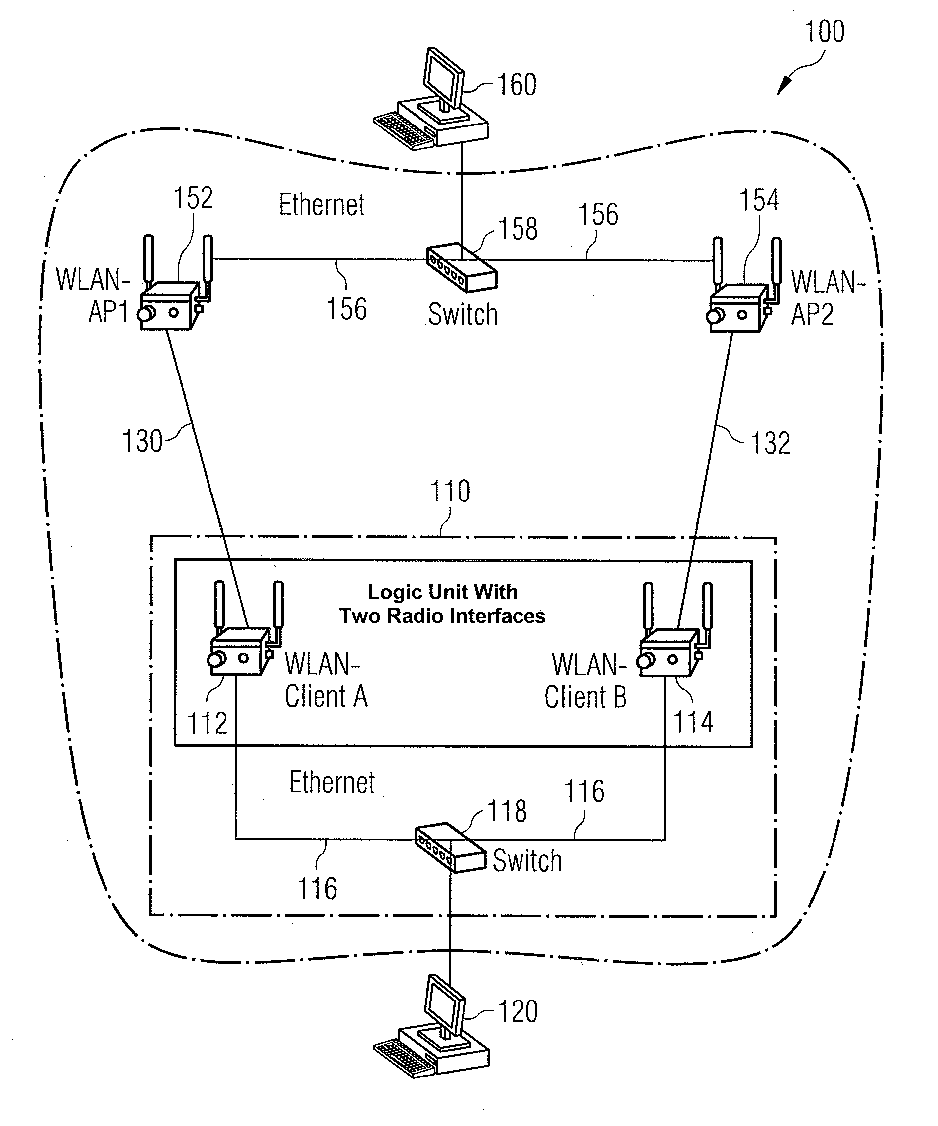
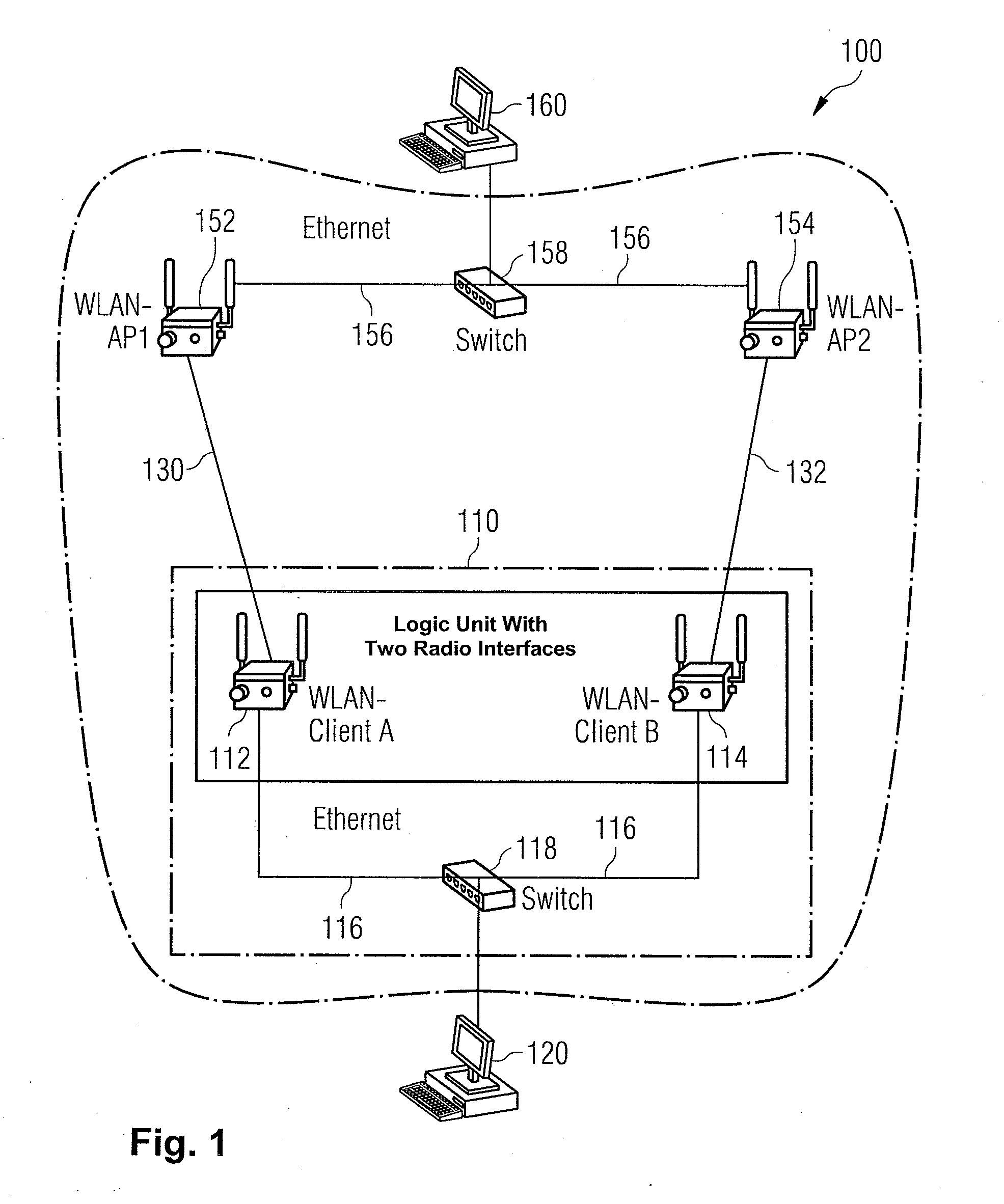
[0051]FIG. 1 is a wired local area network (WLAN) 100 in accordance with the Standard IEEE 802.11 for the transmission of user data from a first communication station 120 to a second communication station 160. The WLAN network 100 comprises a dual client 110, which comprises a first “WLAN client A”112 and a second “WLAN client B”114, which in turn are connected via Ethernet lines 116 and an interposed so-called “switch”118.

[0052]Furthermore, a first “access point”152 (WLAN-AP1) and a second access point 154 (WLAN-AP2) are provided in the WLAN network 100, which are connected via an Ethernet-connection 156 and an interposed switch 158. Furthermore, an active radio link 130 exists between the first WLAN client 112 and the first access point 152.

[0053]In the status of the WLAN network 100 represented in FIG. 1, user data is transmitted from the first communication arrangement 120 to the switch 118 in the dual client 110 and then forwarded over the active radio link 130 from the first W...


PUM


Abstract

A radio station system for a wireless network with at least two access network nodes, wherein a first of the at least two access network node is assigned to the radio station system as an access network node in the wireless network and the radio station system is connected to the first access network node over an active radio link for the transmission of user data. During the existence of the active radio link between a first radio station and the first access network node, a second radio station transmits or exchanges no user data via a radio link with an access network node in the wireless network and at least at times identifies available access network nodes in the wireless network for the radio station system.

Description

BACKGROUND OF THE INVENTION[0001]1. Field of the Invention[0002]The present invention relates to a radio station system for a wireless network, i.e., for an automation, real time and / or industrial wireless network, with at least two access network nodes, where a first of the at least two access network nodes is assigned to the radio station system as an access network node in the wireless network and the radio station system is connected to the first access network node over an active radio link for the transmission of user data.[0003]2. Description of the Related Art[0004]In general, radio station systems are known. For example, US Publication No. 2006 / 0221993 A1 discloses a wireless local area network (WLAN) with a multiplicity of access network nodes designated “access points” and a multiplicity of radio stations in the radio coverage area of the access points. Here, an access point selects a free frequency from a multiplicity of available frequencies, on which it then communicat...

Claims


Application Information

Patent Timeline
Patent Type & Authority Applications(United States)
IPC IPC(8): H04W84/02
CPCH04B1/74
Inventor AKIL, YAHYABENJAMINS, KAIKELLER, STEFANMÜLLER, JÖRGWOLF, MANFRED
Owner SIEMENS AG
Why Eureka
Try Eureka