High-frequency coupler and communication device

Inactive Publication Date: 2011-09-15
SONY CORP
View PDF11 Cites 8 Cited by
  • Summary
  • Abstract
  • Description
  • Claims
  • Application Information

AI Technical Summary

Benefits of technology

[0010]It is desirable for the present invention to provide an excellent high-frequency coupler and a communication device tha

Problems solved by technology

However, if the size of a coupling electrode in a high-frequency coupler is reduced, there is a problem that the communication range diminishes particularly in the transverse direction.
However, if the communication range of the transverse direction is narrow, a target point may be obscured by the shadow of the other equipment when they are adjacent, resulting that the target point is aligned while shifted from the center thereof in the transver

Method used


Image

  • High-frequency coupler and communication device
  • High-frequency coupler and communication device
  • High-frequency coupler and communication device

Examples


Example

[0042]Hereinbelow, an embodiment of the present invention will be described in detail with reference to drawings.

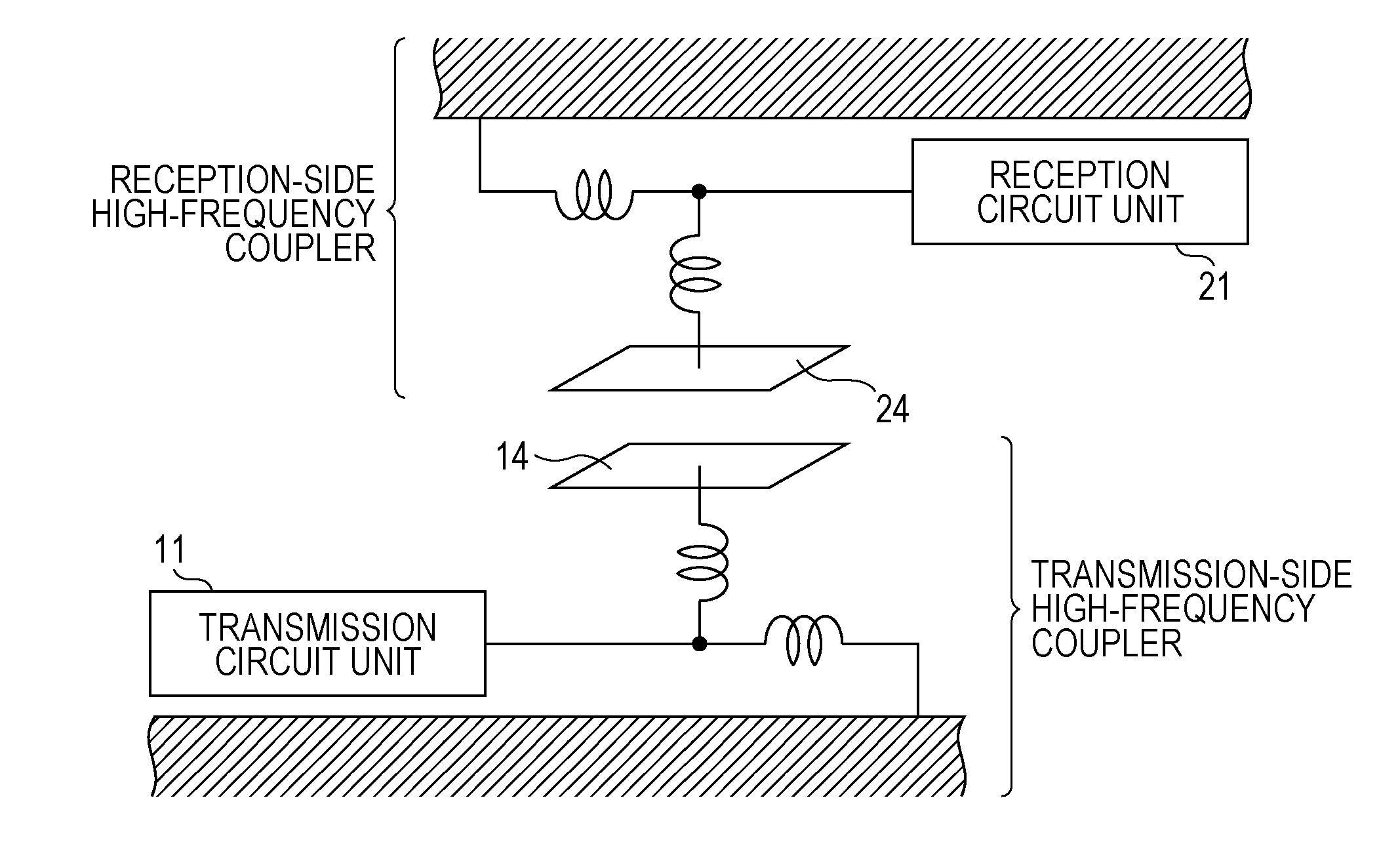
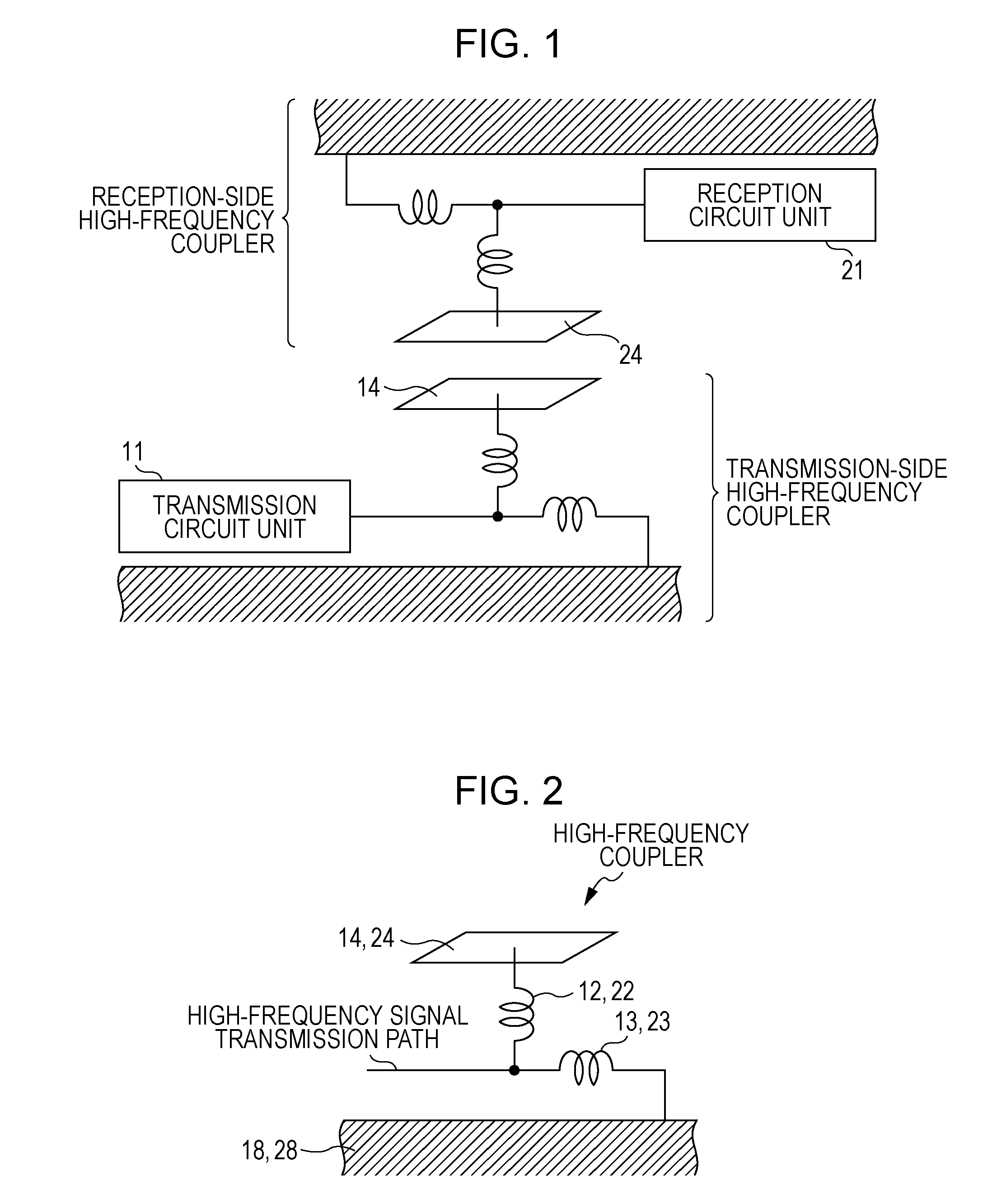
[0043]FIG. 1 is a diagram schematically illustrating the composition of a proximity wireless transfer system in the weak UWB communication method using the action of electric field coupling. In the same drawing, coupling electrodes 14 and 24 used in transmission and reception that belong to a transmitter 10 and a receiver 20 respectively are arranged apart, for example, by about 3 cm (or about ½ of the wavelength of the frequency band being used) from each other in an opposed manner so as to enable electric field coupling. The transmission circuit unit 11 in the transmitter side generates high-frequency transmission signals such as UWB signals based on transmission data when a transmission request is made from an higher level application, and the signals penetrate from the transmitting electrode 14 to the receiving electrode 24 as electric field signals. In addition, the ...


PUM


Abstract

A high-frequency coupler includes a ground, a coupling electrode which faces the ground and is supported so as to be separated by a negligible height with respect to a high-frequency signal, a resonating unit for increasing a current flowing into the coupling electrode, a supporting unit which is connected to the resonating unit, and a short-circuiting unit which short-circuits the tip portions of the coupling electrode, in which an infinitesimal dipole constituted by a line connecting the center of the charges accumulated in the coupling electrode and the center of mirror-image charges accumulated in the ground is formed, and the high-frequency signal is transmitted toward a high-frequency coupler of a communication partner so that the angle θ formed in the direction of the infinitesimal dipole is substantially 0 degrees.

Description

BACKGROUND OF THE INVENTION[0001]1. Field of the Invention[0002]The present invention relates to a high-frequency coupler and a communication device that perform large-volume data transmission in proximity through a weak UWB (Ultra Wide Band) communication method using a high-frequency wide-band, and particularly to a high-frequency coupler and a communication device that secure a communication range in the transverse direction in weak UWB communication using electric field coupling.[0003]2. Description of the Related Art[0004]Non-contact communication has been widely used as a medium for authentication information, electronic money, or other value information. In addition, in recent years, as additional applications of such a non-contact communication system, large-capacity data transmission such as downloading and streaming of moving images, music, or the like can be exemplified. Such large-volume data transmission can also be implemented by the operations of a single user, prefer...

Claims


Application Information

Patent Timeline
IPC IPC(8): H04B1/00H01P1/00
CPCH01P5/085H01Q9/285H01Q9/0485
Inventor WASHIRO, TAKANORI
Owner SONY CORP
Why Eureka
Try Eureka