Autoinjector system

a technology of auto-injector and auto-injector, which is applied in the field of system and method, can solve the problems of inability to perform injections, frightened users by exposed needles, and inability to fully fill syringes, etc., and achieves the effect of not being able to perform so-called multi-tasking operations, reducing the risk of infection, and avoiding infection

Active Publication Date: 2011-09-15
AVANT MEDICAL CORP
View PDF36 Cites 97 Cited by
  • Summary
  • Abstract
  • Description
  • Claims
  • Application Information

AI Technical Summary

Benefits of technology

Operation of the system of the present disclosure requires two separate motors that are individually mounted on the injector. Though they are mechanically independent of each other, the respective operations of these two motors must be coordinated. Specifically, a first motor is used to effect movements of the entire syringe assembly (i.e. syringe chamber, injection needle and plunger are all moved together). On the other hand, a second motor is employed to advance the plunger into the fluid chamber for performing an injection of a fluid medicament.
In a duty cycle of the system, the first motor moves a drive rod into engagement with the syringe. With this engagement, the drive rod also releases the latch that otherwise holds the syringe in the home position. After the syringe has been released, the first motor then advances the syringe in a distal direction on the cassette. This movement inserts the injection needle into a patient. Further, the first motor can be used to abruptly stop the needle when a specified needle depth has been achieved. The first motor can then be used to help stabilize the needle during an injection of the medical medicament from the syringe.

Problems solved by technology

Nevertheless, pre-filled syringes also have a significant drawback in the marketplace.
Specifically, many users are either frightened by an exposed needle or feel they are inherently incapable of performing an injection.
Further, this force must be applied on the plunger of the syringe for what will typically be a relatively longer period of time.
Consequently, springs do not lend themselves for so-called multi-tasking operations.
This can be particularly problematic in situations where it may be desirable to use the same device, at different times, to inject different medications, with different fluid viscosities.
Further, it is desirable that operation of the syringe be limited to only those times when the syringe is properly positioned for an injection.

Method used


Image

  • Autoinjector system
  • Autoinjector system
  • Autoinjector system

Examples


Embodiment Construction

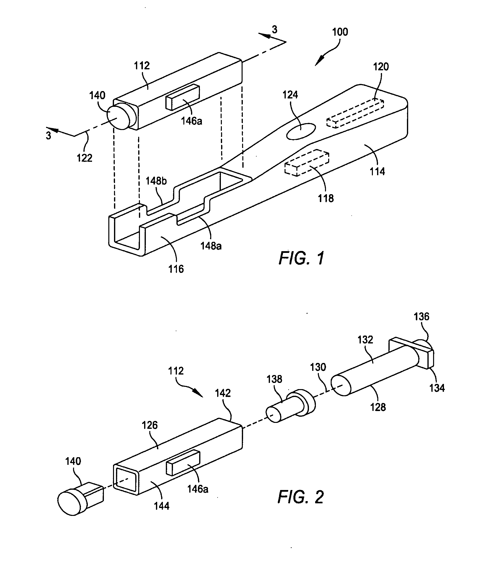
Referring to FIG. 1, an exemplary embodiment of an autoinjector system for injecting a medicament into a user / patient (a user of the system or another person or animal) is shown and is designated by reference numeral 100. The system 100 generally includes a disposable cassette 112 and a re-usable drive mechanism or autoinjector 114. The autoinjector 114 includes a cradle 116 that is dimensioned to receive and hold the cassette 112 on the autoinjector 114. The autoinjector 114 includes a first (injection) motor 118 (shown in phantom) and a section (delivery) motor 120 (also shown in phantom). The motors 118 and 120 may comprise any suitable, well known type of motor including without limitation, stepper motors and reluctance motors. The motors 118 and 120 each includes a drive system for convening the rotary motion of the motor to linear motion. Such drive systems include without limitation, lead screw / worm gear drive systems, rack and pinion drive systems, and any other linear drive...


PUM


Abstract

An autoinjector system for injecting a fluid medicament into a patient includes a re-usable autoinjector, and a disposable cassette loaded with a hypodermic syringe pre-filled with a fluid medicament. The autoinjector includes a first motor for injecting a needle of the hypodermic syringe into the patient and a second motor for expelling the fluid medicament from the syringe.

Description

FIELDThe present disclosure relates to a system and method for injecting medicaments into a patient from a hypodermic syringe. More particularly, the present disclosure relates to an auto-injector and a cassette useable with the auto-injector, which conceals the injection needle of a hypodermic syringe before and after an injection.BACKGROUNDPre-filled hypodermic syringes provide several advantages for the home-use market. These advantages include that pre-filled syringes may be prepared for each medicament with exactly the required dosage. Further, they are easily operated, by merely advancing the stopper of the syringe. Aside from the costs of the particular medication that is being used, pre-filled syringes are also economically manufactured. Consequently, all these advantages make pre-filled syringes commercially appealing.Nevertheless, pre-filled syringes also have a significant drawback in the marketplace. Specifically, many users are either frightened by an exposed needle or ...

Claims


Application Information

Patent Timeline
Patent Type & Authority Applications(United States)
IPC IPC(8): A61M5/20
CPCA61M5/20A61M5/326A61M2005/206A61M2005/208A61M2005/31588A61M5/3204A61M2205/50A61M2205/6045A61M2205/581A61M2205/583A61M2205/13A61M5/3134A61M5/3202A61M2005/2026A61M2005/3142A61M2205/3365
Inventor SLATE, JOHN B.BURK, MICHAEL W.KOERNER, RICHARD J.MAGERS, COREY M.BARNES, ANDREW C.
Owner AVANT MEDICAL CORP
Why Eureka
Try Eureka