
Injection device with controlled needle retraction

Active Publication Date: 2011-10-25
YPSOMED AG
View PDF11 Cites 20 Cited by
  • Summary
  • Abstract
  • Description
  • Claims
  • Application Information

AI Technical Summary

Benefits of technology

Accordingly, one object of the present invention is to provide an injection device, and a method of making and using the device, wherein a user of the device has an easy way of determining when the needle should be retracted.
In some preferred embodiments, the lock element is able to unlatch or disconnect from the engagement with the cut-out when product dispensing has finished, as a result of which the return spring is able to relax by the short distance to generate the signal. In some preferred embodiments, the lock element is blocked to prevent it unlatching from the engagement with the cut-out by the external circumferential surface of the plunger rod moving past the lock element.

Problems solved by technology

As this happens, it may be that the medicament is not or has not been completely injected into the patient's tissue and a small amount is lost.
This is annoying, especially in the case of expensive drugs.
The amount that is lost can also lead to problems with respect to the actual dose administered.

Method used


Image

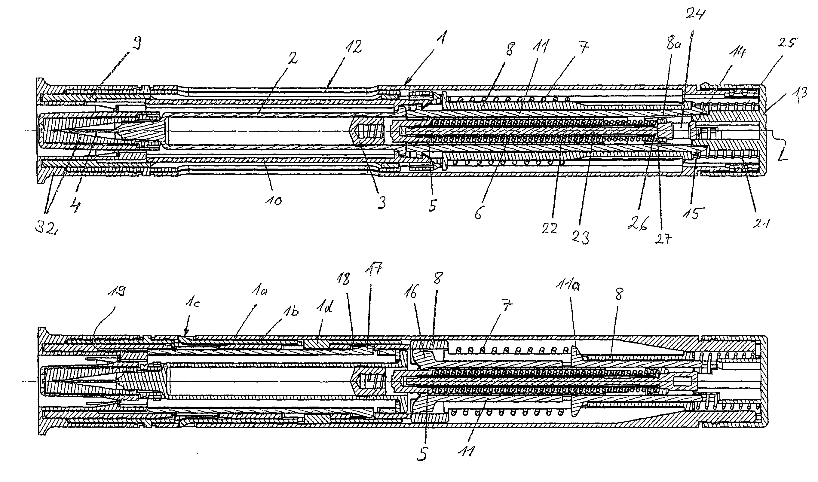
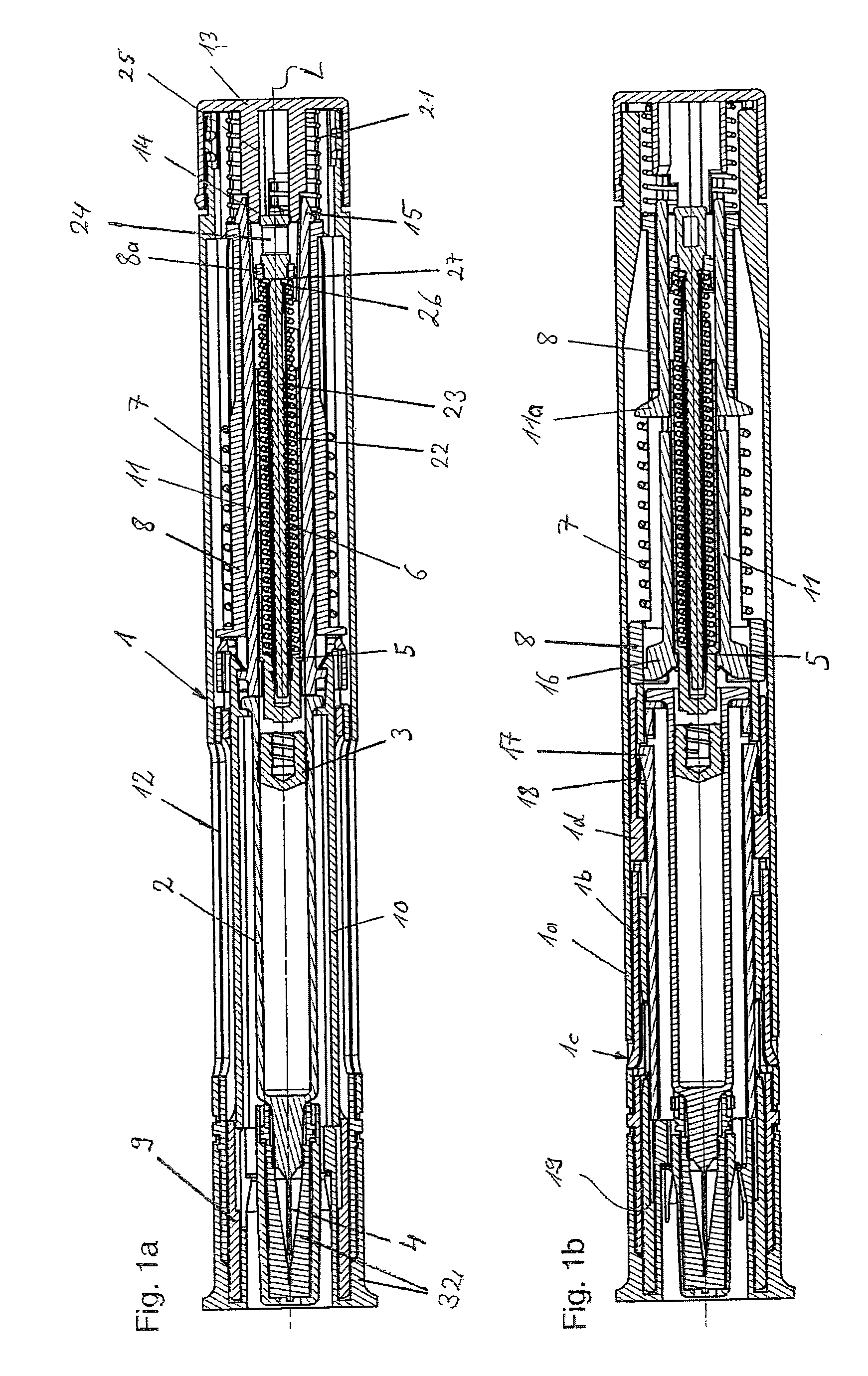
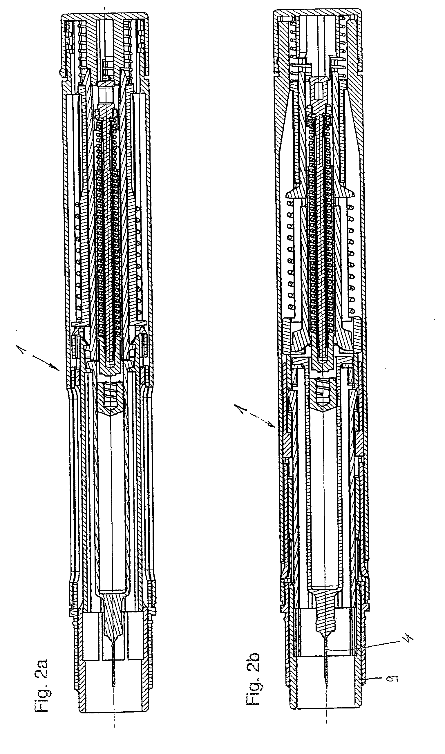
  • Injection device with controlled needle retraction
  • Injection device with controlled needle retraction
  • Injection device with controlled needle retraction

Examples


Embodiment Construction

With regard to fastening, mounting, attaching or connecting components of the present invention, unless specifically described as otherwise, conventional mechanical fasteners and methods may be used. Other appropriate fastening or attachment methods include adhesives, welding and soldering, the latter particularly with regard to the electrical system of the invention, if any. In embodiments with electrical features or components, suitable electrical components and circuitry, wires, wireless components, chips, boards, microprocessors, inputs, outputs, displays, control components, etc. may be used. Generally, unless otherwise indicated, the materials for making embodiments of the invention and / or components thereof may be selected from appropriate materials such as metal, metallic alloys, ceramics, plastics, etc. Unless stated otherwise, positional terms (e.g., up, down, front, rear, distal, proximal, etc.) are descriptive not limiting. Same reference numbers are used to denote same ...


PUM


Abstract

An injection device, in some embodiments an autoinjector, which includes a housing, an actuating sleeve carried by the device to be movable relative to the housing and which can be placed at a point of injection in a position of insertion, an injection needle extendable from the end of the injection device when the injection device is in the position of insertion and moveable into the interior of the injection device, and an actuating cam arranged in an axially fixed manner relative to the injection needle and engageable in a locking recess when the injection device is in the position of insertion to prevent the injection needle from being moved into the interior of the injection device, said actuation cam being releasable from engagement with the locking recess by the actuating sleeve, thereby releasing the injection needle for movement into the injection device.

Description

BACKGROUNDThe present invention relates to devices for injecting, administering, infusing, delivering or dispensing a substance, and to methods of making and using such devices. More particularly, it relates to injection devices for administering a liquid product such as a medicinal substance or a medicament and, more particularly, to an injection device and a method of moving or retracting a needle associated with the injection device from a piercing position in a controlled manner.A known utilization or method of use of injection devices, including automatic injectors, is for a needle to be injected in a patient by a mechanism of the device, after which the product is administered to the patient through the needle. After the product has been successfully dispensed, the needle is covered and / or pulled back into the injection device.For example, U.S. Pat. No. 6,387,078 discloses an injection device in which a needle firstly effects a piercing movement with the aid of a driving sprin...

Claims


Application Information

Patent Timeline
IPC IPC(8): A61M5/20
CPCA61M5/2033A61M5/3204A61M5/3257A61M2005/2013A61M2005/206A61M2005/2073A61M2205/581A61M2205/582
Inventor STREIT, URSINABOLLENBACH, MARKUSHOSTETTLER, PATRICKKUENZLI, DANIEL
Owner YPSOMED AG
Learn More