Cartridge packaging material and cartridge packaging structure

Active Publication Date: 2011-09-22
FUJIFILM CORP
View PDF9 Cites 4 Cited by
  • Summary
  • Abstract
  • Description
  • Claims
  • Application Information

AI Technical Summary

Benefits of technology

[0040]According to the present invention, the one backing plate member separate from the outer case is folded so as to be able to cover the storage case. Since it is possible to prevent the engagement state between the first cutout portion and the first projecting portion as well as the engagement state between the second cutout portion and the second projecting portion from becoming shallow, even if the outer case containing the storage case covered by the backing plate member is dropped so that its ridge portion falls off to the floor first, it is configured so that the storage case hardly moves inside the outer case. Therefore, since an impact force applied to the corner portion of the storage case becomes weak compared with the conventional structure, breakage of the storage case is suppressed. As a result, the deformation and damage of cartridges inside the storage case can be prevented.
[0041]According to the second invention, since the protection effect on the three surfaces of the storage case can be enhanced by the backing plate member, if cartridges are disposed so that portions especially desired to be protected such as access slots of recording media face the third surface of the backing plate member, a protection effect can be enhanced. In this case, an arbitrary portion other than the access slots may be set as the portion

Problems solved by technology

In such a case, a packaging type in which cartridges are each separately stored in cases is troublesome in handling.
Since the outer case contains a large number of cartridges and relatively has a large mass, when the outer case containing the storage case is erroneously dropped due to handling during shipping and the like, the storage case may be damaged.
Further, in particular, in the case where the recording media are tapes, and the tapes are arranged so that their slots (access slots) face the directio

Method used


Image

  • Cartridge packaging material and cartridge packaging structure
  • Cartridge packaging material and cartridge packaging structure
  • Cartridge packaging material and cartridge packaging structure

Examples


modified example of embodiment

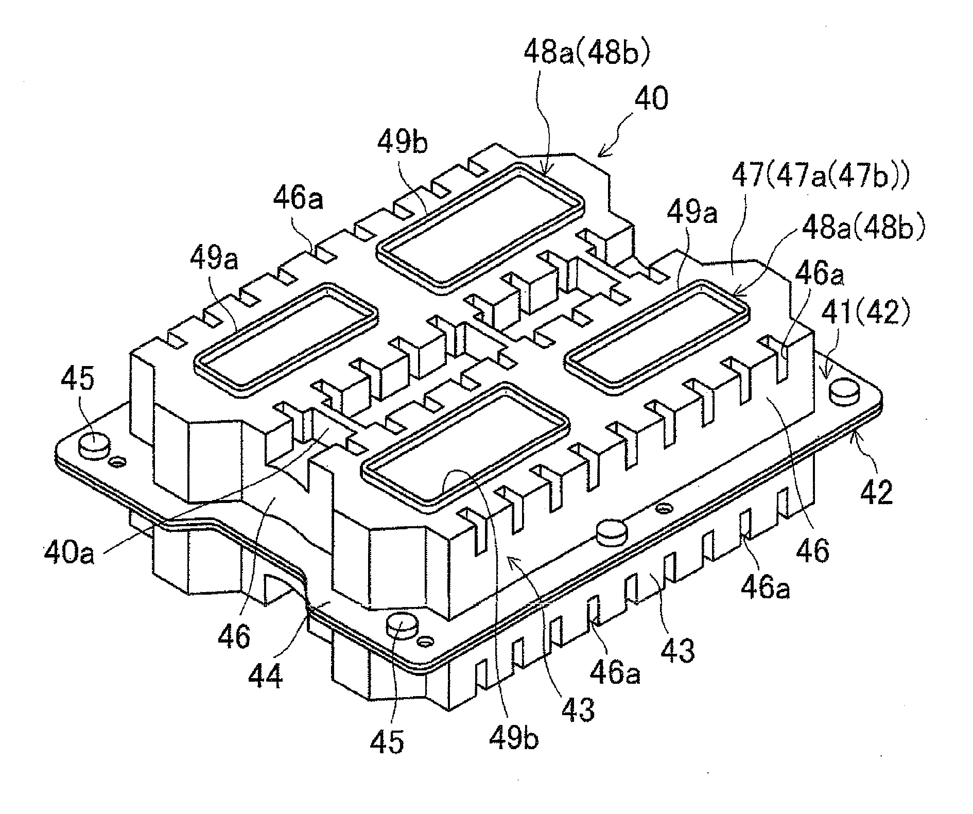
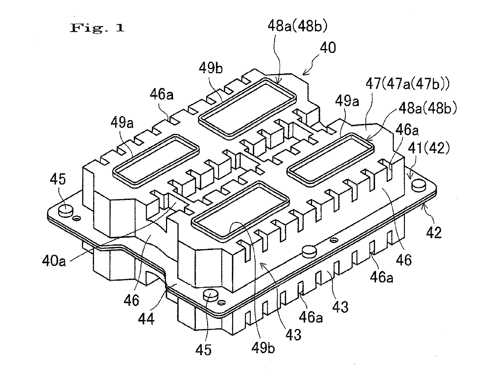
[0110]In the embodiment, the moving amount of the storage case 40 inside the outer case 20 can be restricted by setting other dimensions.

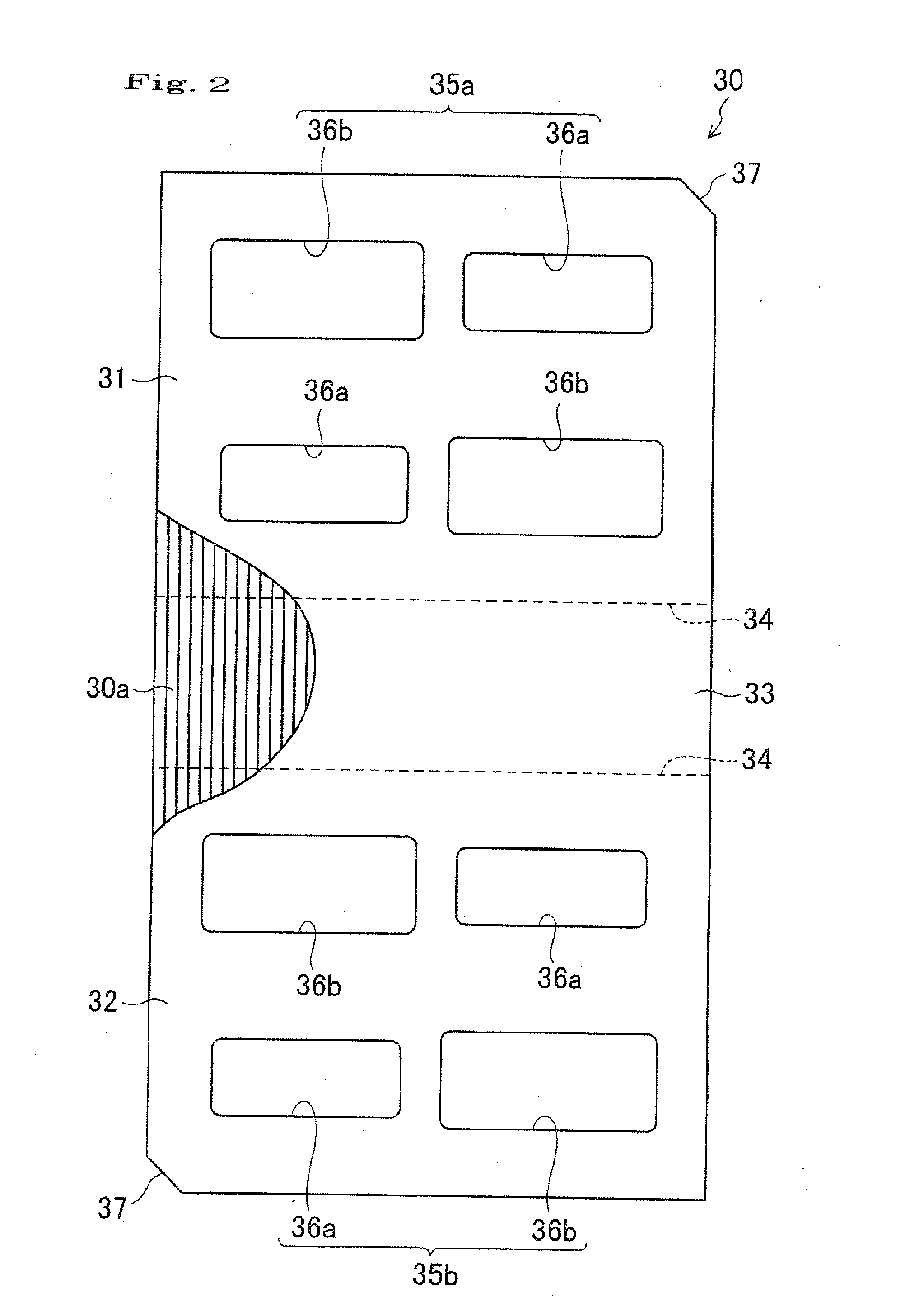
[0111]Specifically, in this modified example, as shown in FIG. 5, the moving amount of the storage case is set based on a gap dimension between the inner surface of the third surface 33 of the backing plate and the side surface of the storage case 40, and a gap dimension between an inner surface of a side plate of the outer case 20 and the side surface of the storage case 40 (namely, the gap dimension between the inner surface of the packaging material 10 and the side surface of the storage case 40, and both of them are represented by “c”).

[0112]As described above, the moving amount of the storage case 40 can be represented by the gap dimension a between the outer edge of the projecting portion 49a, 49b of the storage case 40 and the inner edge of the cutout portion 35a, 35b of the backing plate member 30. In the present modified example, each gap ...


PUM


Abstract

To improve a buffer effect on cartridges as well as to make it possible to suppress deformation or breakage of the cartridges in the case where, after a storage case containing the data recording cartridges has been put in an outer case for packaging, the outer case is dropped. A sheet-shaped member is folded so as to cover an upper surface, a lower surface, and one side surface of a storage case 40 to form a backing plate member 30. The backing plate member 30 is formed with first cutout portions 35a for receiving first projecting portions 48a of an upper surface of the storage case 40, and second cutout portions 35b for receiving second projecting portions 48b of a lower surface the storage case 40.

Description

BACKGROUND OF THE INVENTION[0001]The present invention relates to a packaging material of the type in which a storage case storing data recording cartridges are stored is put in an outer case for protection, and a packaging structure for packaging the storage case using this packaging material.[0002]Traditionally, cartridges for recording media such as disc cartridges and tape cartridges (also simply referred to as cartridges) may be replaced collectively in large numbers for backup of a host computer and the like. In such a case, a packaging type in which cartridges are each separately stored in cases is troublesome in handling. Therefore, considering working efficiency, for example, a bulk specification packaging type in which a plurality of, for example, about twenty cartridges, are collectively stored in one plastic storage case is preferred.[0003]However, with the bulk specification packaging type, the plastic storage cases are directly inserted in an outer case (a corrugated c...

Claims


Application Information

Patent Timeline
IPC IPC(8): B65D85/00
CPCB65D85/00B65D77/0413
Inventor INUGAI, YASUOSUGIFUNE, HIROYUKI
Owner FUJIFILM CORP
Why Eureka
Try Eureka