Fuel cell stack

Inactive Publication Date: 2018-03-29
MITSUBISHI MOTORS CORP
View PDF1 Cites 0 Cited by
  • Summary
  • Abstract
  • Description
  • Claims
  • Application Information

AI Technical Summary

Benefits of technology

[0009]Illustrative aspects of the present invention provide a f

Problems solved by technology

However, a metal separator may be insufficient in corrosion resistance depending on the voltage condition of the fuel cell.
For example, in a case where voltage of the fuel cell is relatively high, the separator is easily corroded due to the high voltage.
Resin separators are superior to metal separators in corrosion resistance but lo

Method used


Image

  • Fuel cell stack
  • Fuel cell stack
  • Fuel cell stack

Examples


Embodiment Construction

[0014]Hereinafter, embodiments of the present invention will be described in detail with reference to the drawings.

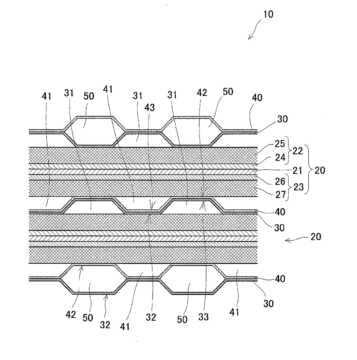
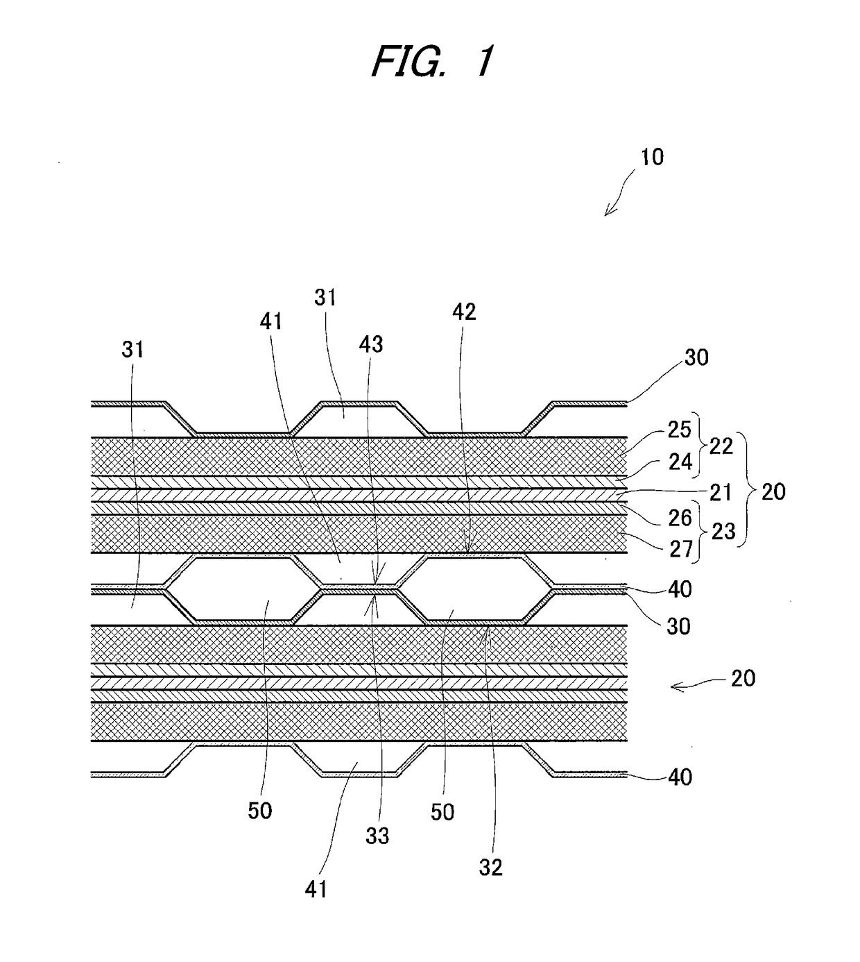
[0015]As shown in FIG. 1, a fuel cell stack 10 according to an embodiment of the present invention has a stack of cells 20 and is configured as, for example, a polymer electrolyte fuel cell. The number of the cells 20 forming the fuel cell stack 10 is not particularly limited, and may be determined as appropriate. FIG. 1 shows two cells 20 as part of the fuel cell stack 10.

[0016]Each cell 20 has an electrolyte membrane 21 (e.g., a solid polymer electrolyte membrane), an anode 22 serving as a fuel electrode on one side of the electrolyte membrane 21, and a cathode 23 serving an oxidant electrode on the other side of the electrolyte membrane 21. In other words, the anode 22 and the cathode 23 are provided so as to hold the electrolyte membrane 21 between the anode 22 and the cathode 23.

[0017]The anode 22 has an electrode catalyst layer 24 (anode-side catalyst layer) conta...


PUM

PropertyMeasurementUnit
Electrical conductivityaaaaaaaaaa
Shapeaaaaaaaaaa
Porosityaaaaaaaaaa

Abstract

A fuel cell stack has a stack of cells and separators interposed between the cells. Each cell has an electrolyte membrane, an anode provided on one side of the electrolyte membrane, and a cathode provided on another side of the electrolyte membrane. The separators include a metal separator provided on an outer side of the anode and a resin separator provided on an outer side of the cathode.

Description

CROSS-REFERENCE TO RELATED APPLICATION[0001]The present application claims priority from Japanese Patent Application No. 2016-190174 filed on Sep. 28, 2016, the entire content of which is incorporated herein by reference.FIELD OF INVENTION[0002]The present invention relates to a fuel cell stack having a stack of cells for generating electric power through a reaction of hydrogen and oxygen.RELATED ART[0003]Related art cells include a polymer electrolyte fuel cell configured to generate electromotive force through an electrochemical reaction of hydrogen-containing fuel gas supplied to an anode (a fuel electrode) and oxygen-containing oxidizing gas (e.g., air) supplied to a cathode (an oxidant electrode). The fuel cell has a fuel cell stack in which cells are stacked with separators being interposed therebetween, each cell having a solid polymer membrane serving as an electrolyte membrane between the anode and the cathode. Each of the cathode and the anode includes a catalyst layer and...

Claims


Application Information

Patent Timeline
IPC IPC(8): H01M8/04H01M8/24H01M8/0247
CPCH01M8/04H01M8/2459H01M8/0247H01M8/1004H01M8/0206H01M8/0221H01M8/0228H01M8/0245H01M8/0267H01M2008/1095Y02E60/50
Inventor HIRAMITSU, YUSUKETASHIRO, KEISUKE
Owner MITSUBISHI MOTORS CORP
Why Eureka
Try Eureka