Variable valve timing apparatus and control method therefor

a timing apparatus and valve technology, applied in the direction of valve drives, electric control, instruments, etc., can solve the problem of difficult to obtain torque for rotating the camshaft, and achieve the effect of suppressing power consumption and heat generation

Active Publication Date: 2009-08-06
TOYOTA JIDOSHA KK +1
View PDF7 Cites 1 Cited by
  • Summary
  • Abstract
  • Description
  • Claims
  • Application Information

AI Technical Summary

Benefits of technology

[0026]In accordance with the variable valve timing apparatus, for the variable valve timing apparatus having the actuator o

Problems solved by technology

Particularly, in the case where the electric motor is used to rotate the camshaft, the torque for rotating

Method used


Image

  • Variable valve timing apparatus and control method therefor
  • Variable valve timing apparatus and control method therefor
  • Variable valve timing apparatus and control method therefor

Examples


Embodiment Construction

[0039]With reference to the drawings, embodiments of the present invention are hereinafter described. In the following description, like components are denoted by like reference characters. They are also named identically and function identically. Therefore, a detailed description thereof is not repeated.

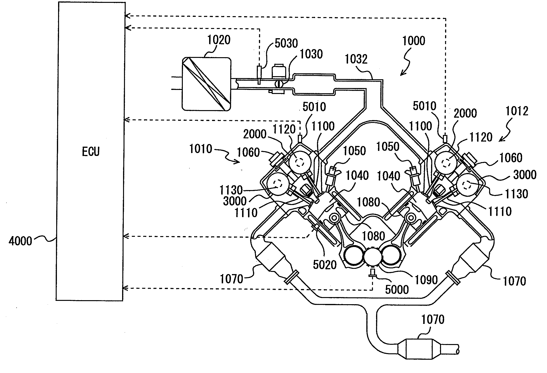
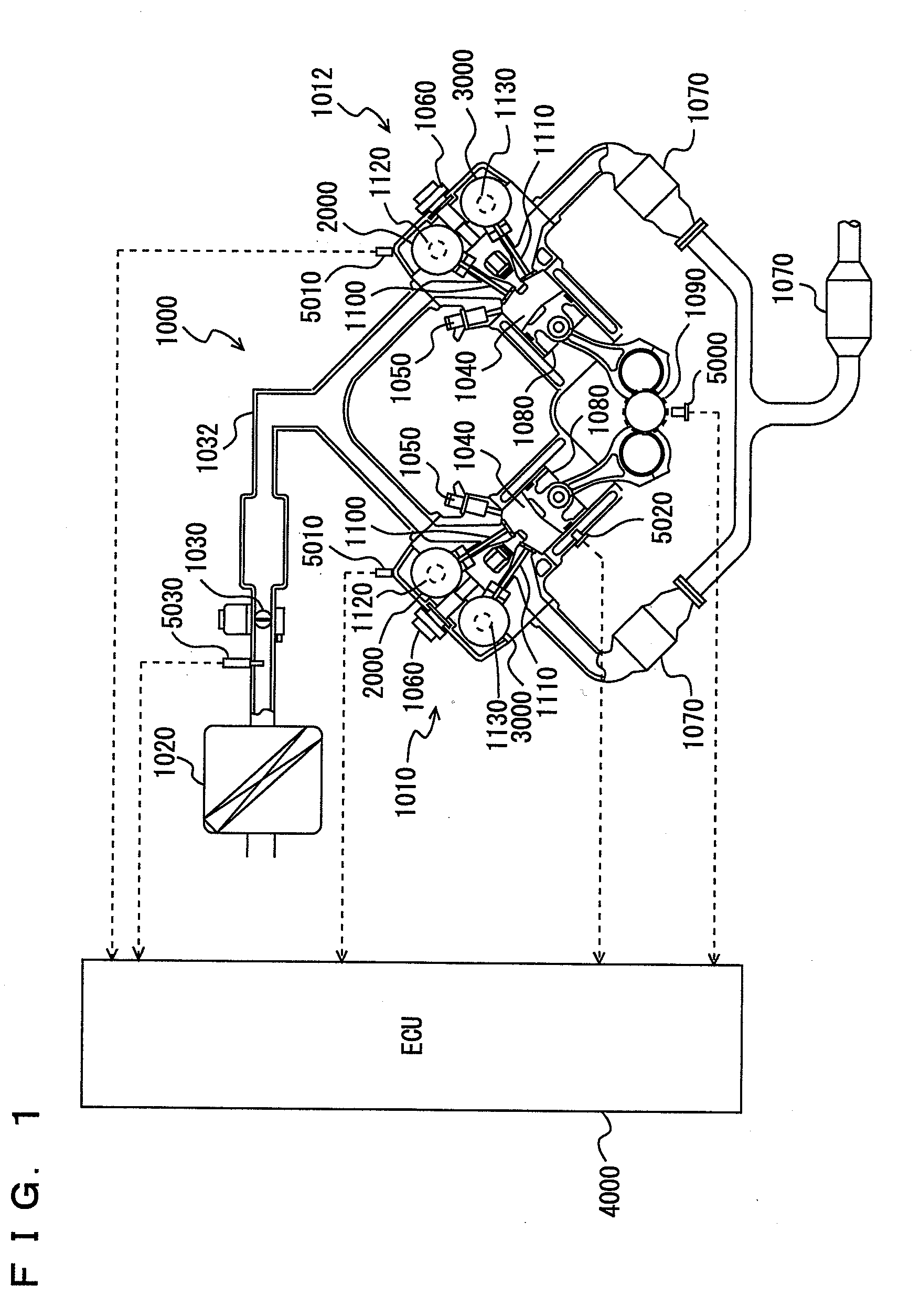
[0040]Referring to FIG. 1, a description is given of an engine of a vehicle on which a variable valve timing apparatus is mounted, according to an embodiment of the present invention.

[0041]Engine 1000 is a V-type 8-cylinder engine having an “A” bank 1010 and a “B” bank 1012 each including a group of four cylinders. Here, any engine other than the V8 engine may be used.

[0042]Into engine 1000, air is sucked from an air cleaner 1020. The quantity of sucked air is adjusted by a throttle valve 1030. Throttle valve 1030 is an electronic throttle valve driven by a motor.

[0043]The air is supplied through an intake manifold 1032 into a cylinder 1040. The air is mixed with fuel in cylinder 10...


PUM


Abstract

An ECU executes a program including the steps of: controlling, when the phase of an intake valve is a phase advanced relative to a threshold value CA (FF) (NO in S106), an electric motor operating an intake VVT mechanism by feedback control (S202); and controlling, when the phase of the intake valve is a phase retarded relative to the threshold value CA (FF) (YES in S106), the electric motor by feed-forward control (S200). Under the feed-forward control, a duty command value is output that is smaller than an upper limit of a duty command value under the feedback control.

Description

TECHNICAL FIELD[0001]The present invention relates to a variable valve timing apparatus and a control method therefor. In particular, the invention relates to a variable valve timing apparatus using an actuator operating at a torque according to a command value to change the timing at which a valve is opened / closed, and to a control method therefor.BACKGROUND ART[0002]VVT (Variable Valve Timing) has conventionally been known that changes the phase (crank angle) in (at) which an intake valve or an exhaust valve is opened / closed, according to an operating condition. Generally, the VVT changes the phase by rotating, relative to a sprocket or the like, a camshaft that causes the intake valve or exhaust valve to open / close. The camshaft is rotated by such an actuator as hydraulic or electric motor. Particularly, in the case where the electric motor is used to rotate the camshaft, the torque for rotating the camshaft is difficult to obtain, as compared with the case where the camshaft is ...

Claims


Application Information

Patent Timeline
IPC IPC(8): F01L1/34F02D41/00
CPCF01L1/352F01L1/34F02D13/02F02D41/14
Inventor MASHIKI, ZENICHIROINOUE, YASUMICHITAKAGI, NOBORUURUSHIHATA, HARUYUKI
Owner TOYOTA JIDOSHA KK
Why Eureka
Try Eureka