
Manufacturing method of gas sensor

a manufacturing method and sensor technology, applied in the direction of manufacturing tools, material electrochemical variables, instruments, etc., can solve the problems of direct contact and entanglement of directly opposed metal terminals, deterioration of workability, and so as to achieve effective suppression of metal terminal breakage or deformation and improve workability

Active Publication Date: 2020-12-29
NGK SPARK PLUG CO LTD
View PDF4 Cites 0 Cited by
  • Summary
  • Abstract
  • Description
  • Claims
  • Application Information

AI Technical Summary

Benefits of technology

The present invention is aimed at improving the manufacturing process of gas sensors by preventing breakage or deformation of the metal terminals during the mounting process in the separator. The technical effects of this invention are improved workability and higher reliability of the gas sensor during its use.

Problems solved by technology

During the mounting of the metal terminals in the separator before the insertion of the sensor element between the metal terminals, there may occur contact and entanglement of the directly opposed metal terminals.
This leads to problems such as breakage or deformation of the metal terminal and deterioration of workability.

Method used


Image

  • Manufacturing method of gas sensor
  • Manufacturing method of gas sensor
  • Manufacturing method of gas sensor

Examples


first embodiment

[0075]In the first embodiment, the protrusion 310 is substantially H-shaped when viewed from the upper side as shown in FIG. 5. More specifically, the protrusion 310 includes: a rectangular column portion 314 located in the center thereof; two plate-shaped flat portions 312 extending in opposite directions from opposite surfaces of the rectangular column portion 314; and two lateral wall portions 316 extending from respective ends of the flat portions 312 in directions perpendicular to the flat portions 312 and each having both ends in flush with the other two opposite surfaces of the rectangular column portion 314. The rectangular column portion 314 and the lateral wall portions 316 protrude from plate surfaces of the flat portion 312. The two flat portions 312 are located at such positions as to, when the metal terminals 21a, 21b, 22a and 22b are inserted in the separator 166 installed in the installation space 300h, correspond to opposed surfaces of the contact regions 21p of the...

second embodiment

[0090]As shown in FIGS. 9 and 11, a part of the outer circumference of the installation space 400h is formed as a straight portion 400s; and a straight portion 166t is formed on the separator 166 so as to be engageable with the straight portion 400s. By engagement of the straight portions 400s and 166t, the separator 166 is restricted from rotating in the circumferential rotation as in the case of the straight portions 300s and 166t. The straight portions 400s and 116 thus correspond to the claimed first and second separator restriction parts in the

[0091]When the metal terminals 21a, 21b, 22a and 22b are installed in the installation space 400h of the second mounting jig 400 so that the flat portion 412 is interposed between the contact regions 21p of the metal terminals 21a, 21b, 22a and 22b in the after-mentioned metal terminal installation step, the metal terminals 21a and 21b are aligned on one main surface of the flat portion 412; and the metal terminals 22a and 22b are aligned...


PUM

PropertyMeasurementUnit
thicknessaaaaaaaaaa
inner diameteraaaaaaaaaa
outer diameteraaaaaaaaaa

Abstract

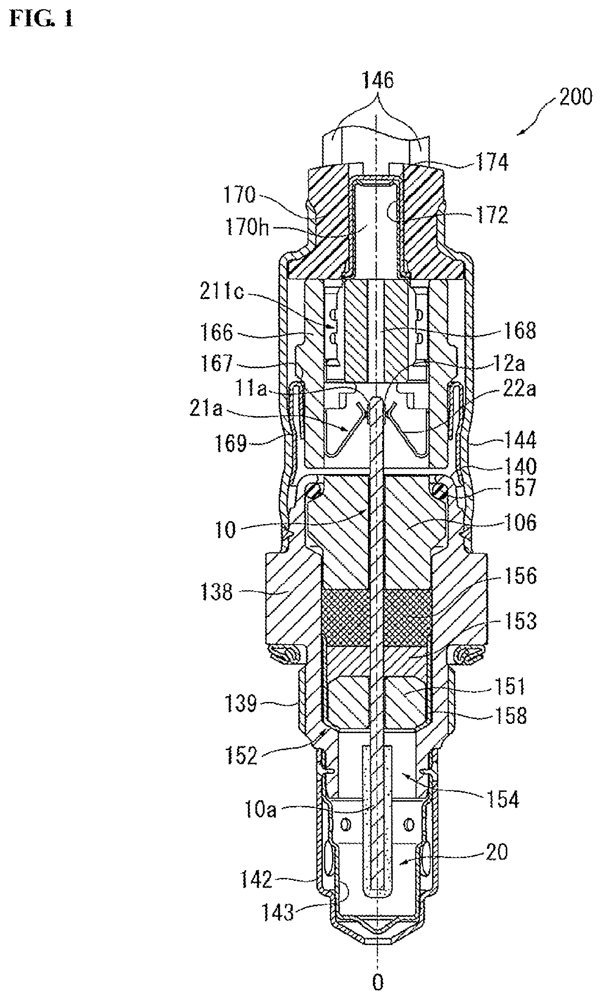
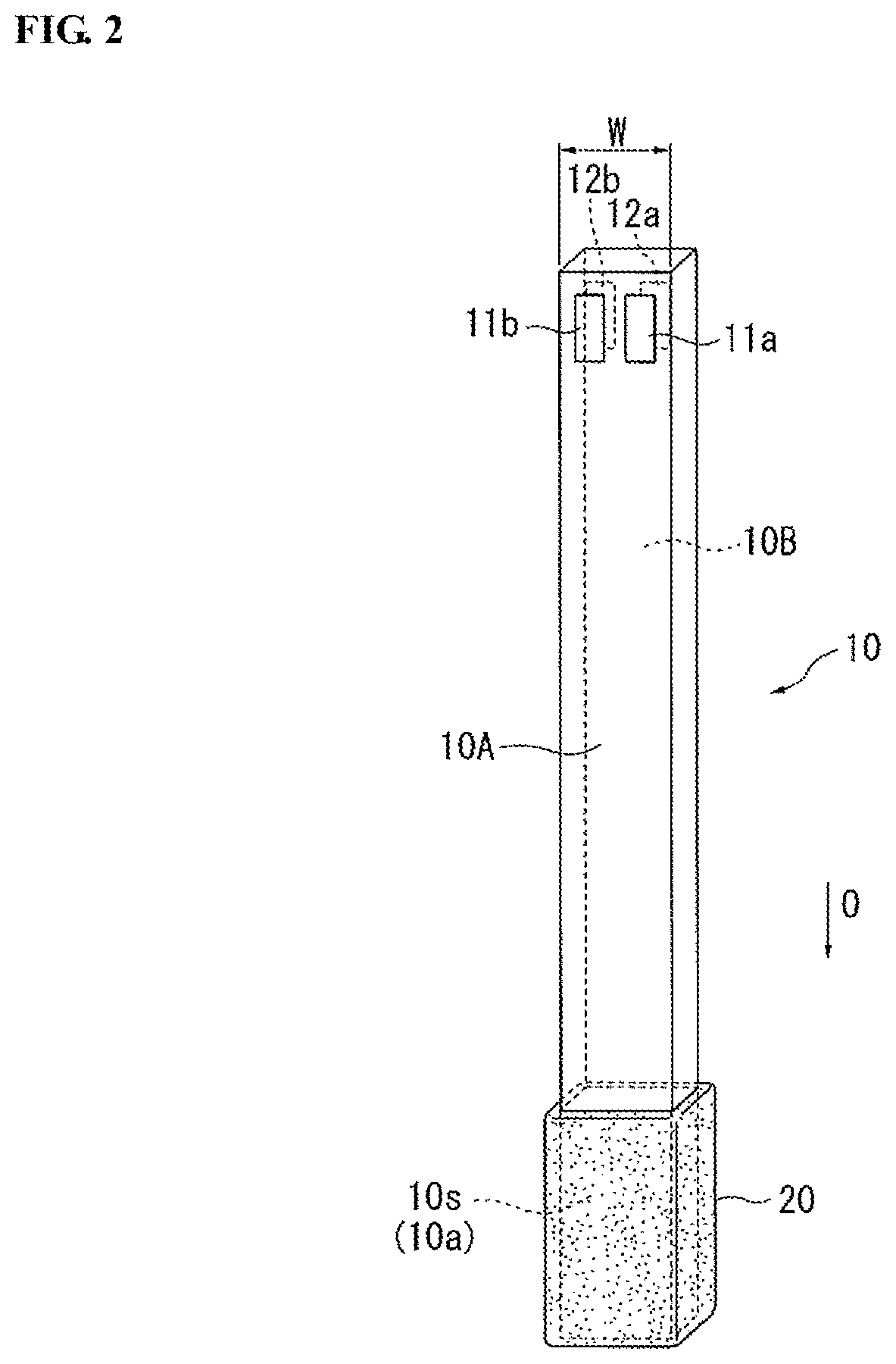
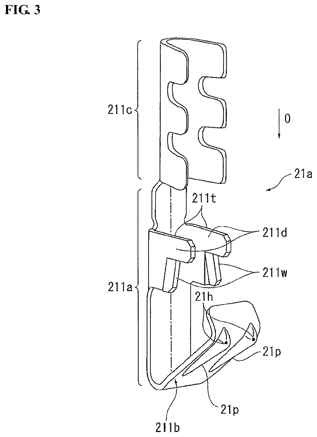
Disclosed is a manufacturing method of a gas sensor. The gas sensor has a plate-shaped sensor element with at least one pair of electrode pads, a separator disposed around the sensor element, and at least one pair of opposed metal terminals held in an insertion hole of the separator and electrically connected at contact regions thereof to the respective electrode pads. The manufacturing method includes mounting the metal terminals in the insertion hole of the separator with the use of a mounting jig. The mounting jig has a flat portion interposed between the contact regions of the metal terminals during the mounting of the metal terminals in the separator so as to prevent contact and entanglement of the opposed metal terminals.

Description

FIELD OF THE INVENTION[0001]The present invention relates to a method for manufacturing a gas sensor with a sensor element capable of detecting the concentration of a specific gas component in a gas under measurement. Hereinafter, the term “front” refers to a gas sensing side with respect to the direction of an axis of a gas sensor; and the term “rear” refers to a side opposite the front side.BACKGROUND OF THE INVENTION[0002]As a gas sensor for detecting the concentration of a specific gas component (such as oxygen or NOx) in an exhaust gas of a vehicle, there is known a gas sensor of the type having a plate-shaped sensor element equipped with a solid electrolyte body. Japanese Laid-Open Patent Publication No. 2013-181768 (FIGS. 1 and 4) discloses one such type of gas sensor that includes: a plate-shaped sensor element having at least one pair of electrode pads on opposite main surfaces of a rear end part thereof; and at least one pair of metal terminals brought into electrical cont...

Claims


Application Information

Patent Timeline
Patent Type & Authority Patents(United States)
IPC IPC(8): G01N27/407G01N27/406B23P19/04G01N33/00
CPCG01N27/4062G01N33/0027G01N27/407B23P19/04G01N27/4077G01N27/4071Y10T29/49147G01N27/26
Inventor OBA, TAKEHIROOKUMURA, TATSUYA
Owner NGK SPARK PLUG CO LTD
Learn More