
Stereoscopic visualization system

Active Publication Date: 2011-09-22
VIKING SYST
View PDF13 Cites 39 Cited by
  • Summary
  • Abstract
  • Description
  • Claims
  • Application Information

AI Technical Summary

Benefits of technology

[0023]The present invention provides a new and improved stereoscopic visualization system which can address the foregoing issues of convergence in medical (e.g., endoscopic) and related applications. Among other

Problems solved by technology

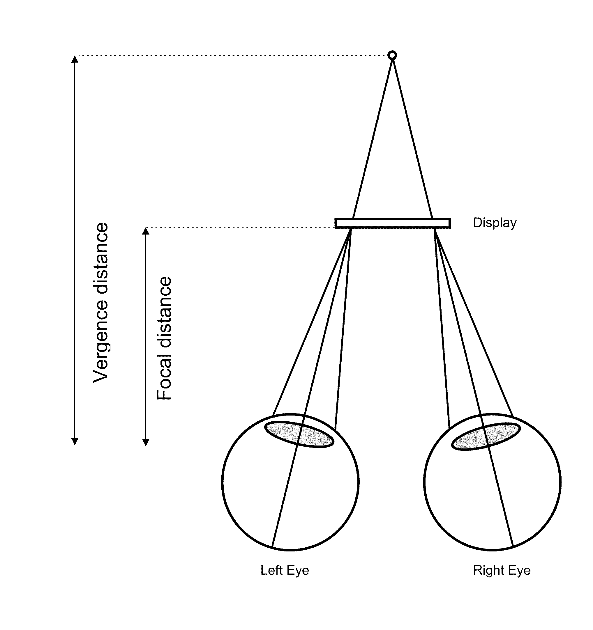
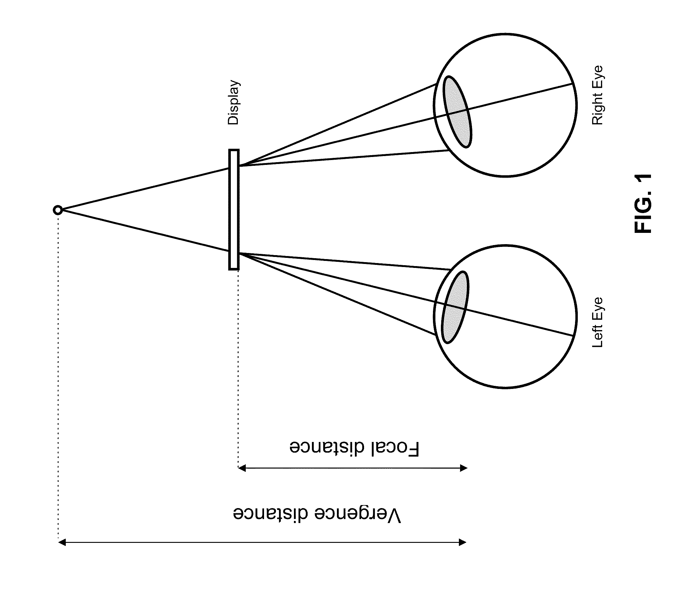
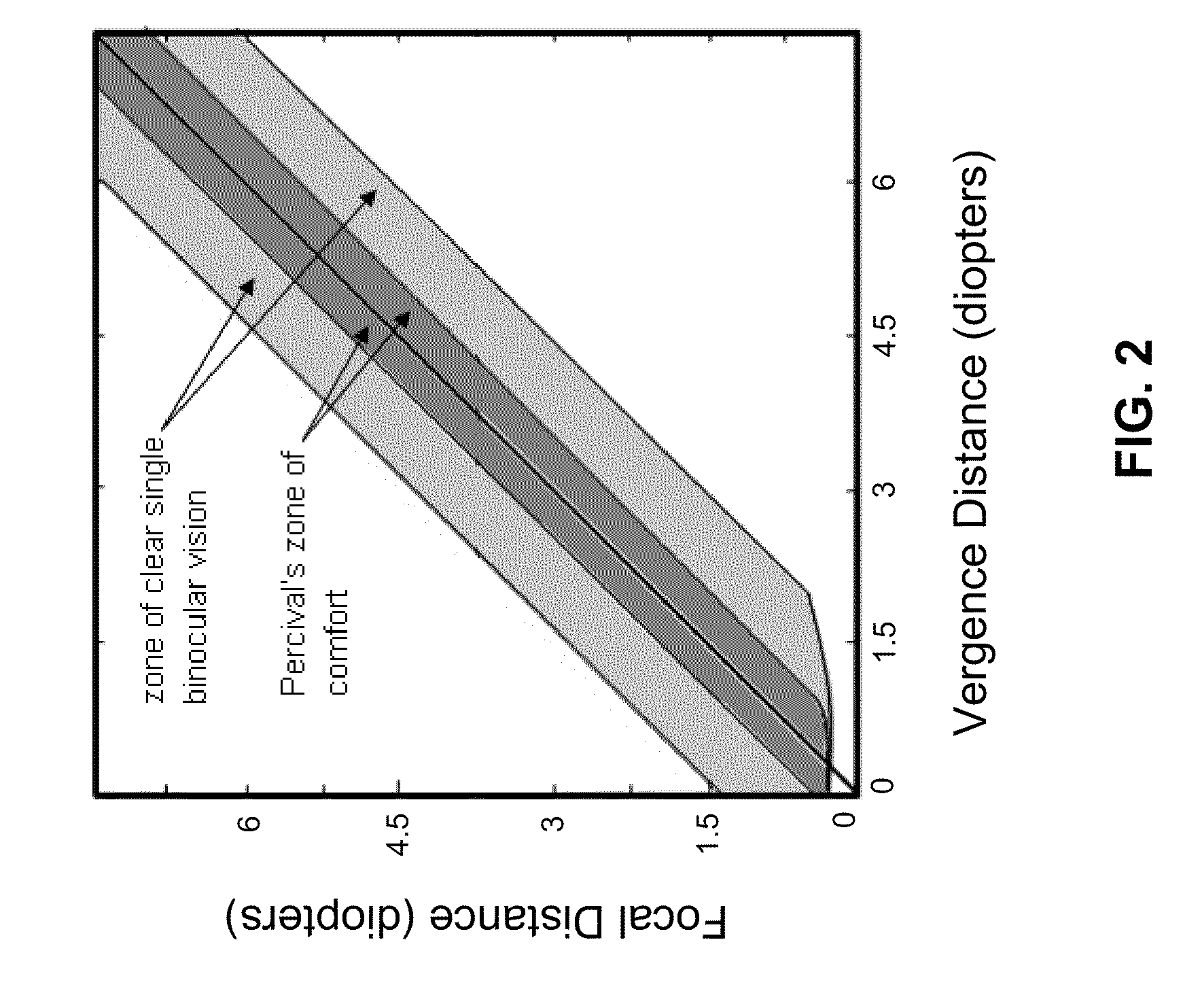
One of the main problems associated with stereoscopic television is the disruption of the normal correlation between human eye accommodation and vergence between the two eyes of the viewer.
However, this correlation between the focusing of the eyes and their convergence is usually disrupted in stereoscopic video applications.
This break in the linkage between eye focus and convergence causes eye strain and fatigue for the viewer.
The drawback of a conventional stereo camera is that when the camera is focused to any other point which is at a distance different from the point of convergence, then the point in the center of the display device will have non-zero parallax, thereby breaking the normal link between eye accommodation and convergence.
This break in the normal link between eye accommodation and convergence causes eye strain and fatigue for the viewer.
In some situations, e.g., where the conventional stereo camera only needs to be used for brief periods of time, and / or where it is not necessary to view an image with significant precision, and / or where the parallax is relatively nominal, this break in the normal link between eye accommodation and convergence may cause only modest levels of eye strain and fatigue for the viewer and a conventional stereo camera may be acceptable.
However, in medical (e.g., endoscopic) applications where the stereo camera must be used for long periods of time, with great precision and where the parallax is frequently substantial, the break in the link between eye accommodation and convergence may cause significant levels of eye strain and fatigue for the viewer, and a conventional stereo camera may be unsatisfactory.

Method used


Image

  • Stereoscopic visualization system
  • Stereoscopic visualization system
  • Stereoscopic visualization system

Examples


Embodiment Construction

Novel Stereoscopic Visualization System Wherein Parallax is Adjusted by Adjusting the Physical Dispositions of the Left Image Sensor and the Right Image Sensor in Accordance with the Focal Point of the Stereoscopic Visualization System

[0096]Assuming that the user will most likely try to bring the image of the most important part of the scene (e.g., the tissue under treatment) into proper focus and into the center of the display, it is preferable to correlate focus and vergence for the center of the displayed image.

[0097]Thus, and looking now at FIG. 5, in one form of the present invention, there is provided a novel stereoscopic visualization system 26 which is configured to maintain the link between focus and vergence for the center of the displayed image. Stereoscopic visualization system 26 generally comprises the endoscope 21 for acquiring a stereo view of a scene, a novel stereo camera 28 for capturing the image obtained by endoscope 21, electronic processing apparatus 29 (which...


PUM


Abstract

Apparatus for presenting a stereoscopic image to a viewer, the apparatus comprising:a stereoscopic video system comprising:first and second image sensors for acquiring, respectively, first and second images of a scene;a display system for displaying the first image to the first eye of the viewer and the second image to the second eye of the viewer; andparallax adjusting means for adjusting the parallax between the first and second images.A method for presenting a stereoscopic image to a viewer, the method comprising:providing a stereoscopic video system comprising:first and second image sensors for acquiring, respectively, first and second images of a scene;a display system for displaying the first image to the first eye of the viewer and the second image to the second eye of the viewer; andparallax adjusting means for adjusting the parallax between the first and second images; andoperating the stereoscopic video system so as to provide a stereoscopic image to the user wherein parallax has been adjusted.

Description

REFERENCE TO PENDING PRIOR PATENT APPLICATION[0001]This patent application claims benefit of pending prior U.S. Provisional Patent Application Ser. No. 61 / 313,220, filed Mar. 12, 2010 by Yuri Kazakevich et al. for STEREOSCOPIC VIDEO CAMERA (Attorney's Docket No. VIKING-2 PROV), which patent application is hereby incorporated herein by reference.FIELD OF THE INVENTION[0002]This invention relates to visualization systems in general, and more particularly to stereoscopic visualization systems.BACKGROUND OF THE INVENTION[0003]One of the main problems associated with stereoscopic television is the disruption of the normal correlation between human eye accommodation and vergence between the two eyes of the viewer. Specifically, in normal visual experience, the human eyes are accommodated (i.e., focused) to the object of observation and, at the same time, the two eyes are converged on the same object. Therefore the object of observation is projected on corresponding areas of the two retina...

Claims


Application Information

Patent Timeline
IPC IPC(8): H04N13/00
CPCA61B1/0005A61B1/042A61B1/00193A61B1/00188H04N13/239H04N13/128H04N13/398A61B1/00009A61B1/04G02B23/2415G02B23/2484
Inventor KAZAKEVICH, YURIKENNEDY, JOHN E.
Owner VIKING SYST
Learn More