Lubricant applying device, image forming apparatus, process unit, and solid lubricant

a technology of image forming apparatus and lubricant, applied in the direction of instruments, optics, electrographic processes, etc., can solve the problems of solid lubricant being likely to break or chip, and negative influence on image quality

Inactive Publication Date: 2011-09-22
RICOH KK
View PDF14 Cites 42 Cited by
  • Summary
  • Abstract
  • Description
  • Claims
  • Application Information

AI Technical Summary

Benefits of technology

[0013]It is an object of the present invention to at least partially solve the problems in the conventional technology.

Problems solved by technology

However, if the thickness significantly decreases, the solid lubricant is likely to break or chip.
Therefore, in the rotation axis direction of the photosensitive element, the large deviation is generated in the application amount of the lubricant, which results in negative influence on an image quality.
However, if the thickness extraordinarily decreases, the solid lubricant is likely to break or chip.
However, depending on the internal layout of the device, the sensor may not be disposed at the position where the sensor faces the solid lubricant in the thickness direction.
In such a case, it may be difficult to detect the moving amount of the solid lubricant in the thickness direction.

Method used


Image

  • Lubricant applying device, image forming apparatus, process unit, and solid lubricant
  • Lubricant applying device, image forming apparatus, process unit, and solid lubricant
  • Lubricant applying device, image forming apparatus, process unit, and solid lubricant

Examples


first embodiment

[0131]An embodiment of an electrophotography printer (hereinafter, simply referred to as printer) as an image forming apparatus where the present invention is applied will be described hereinafter.

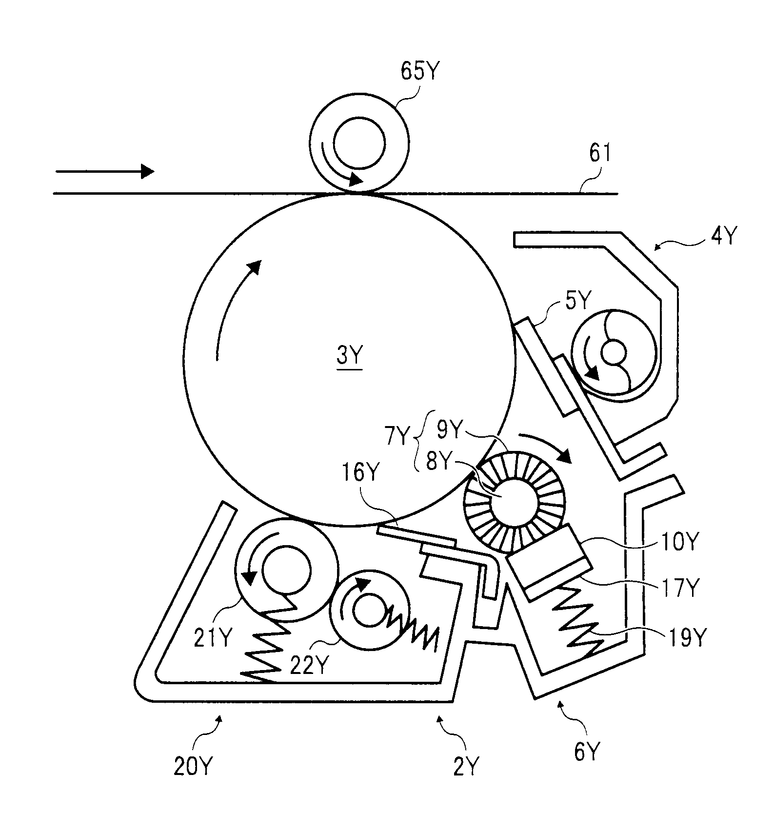
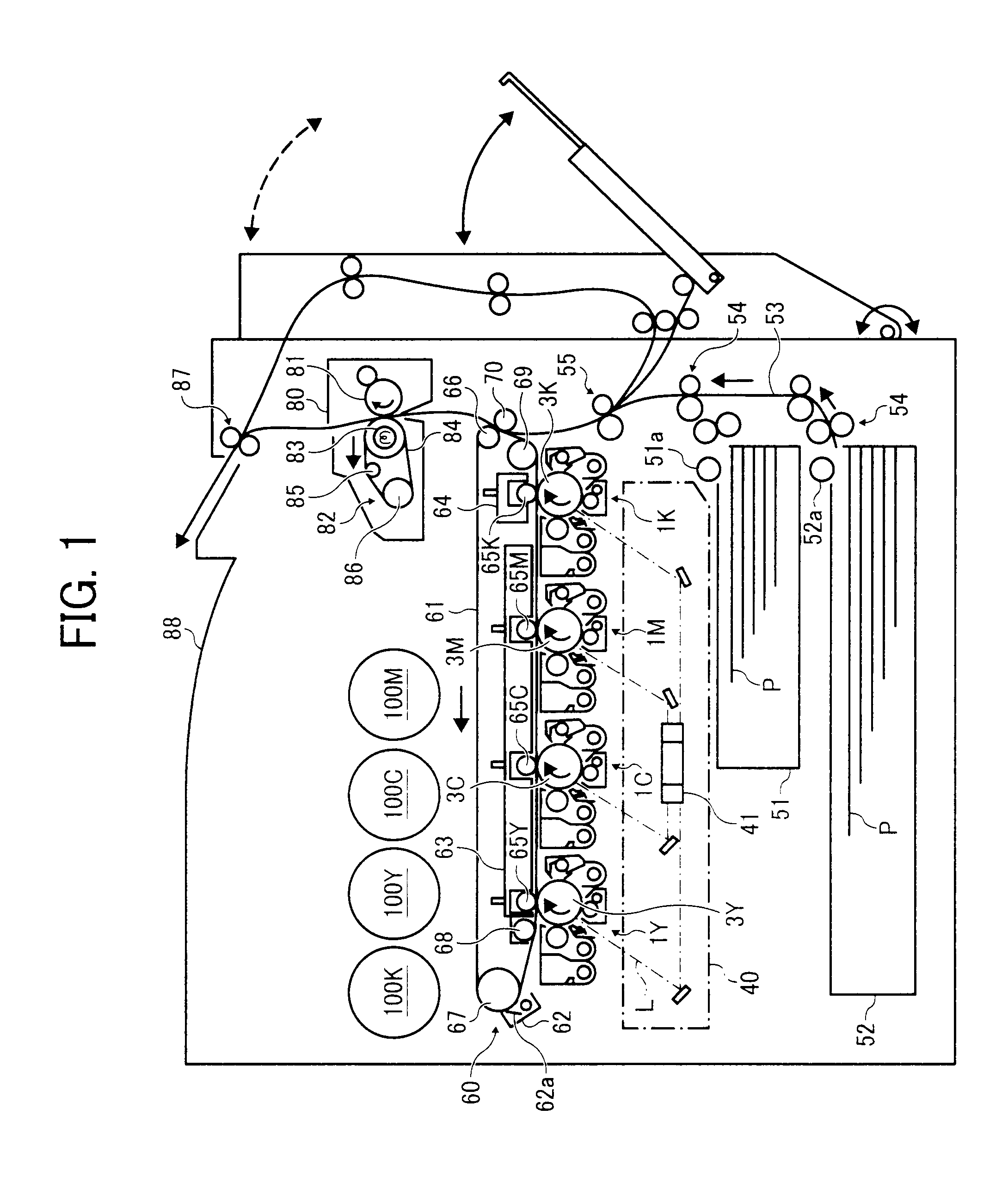
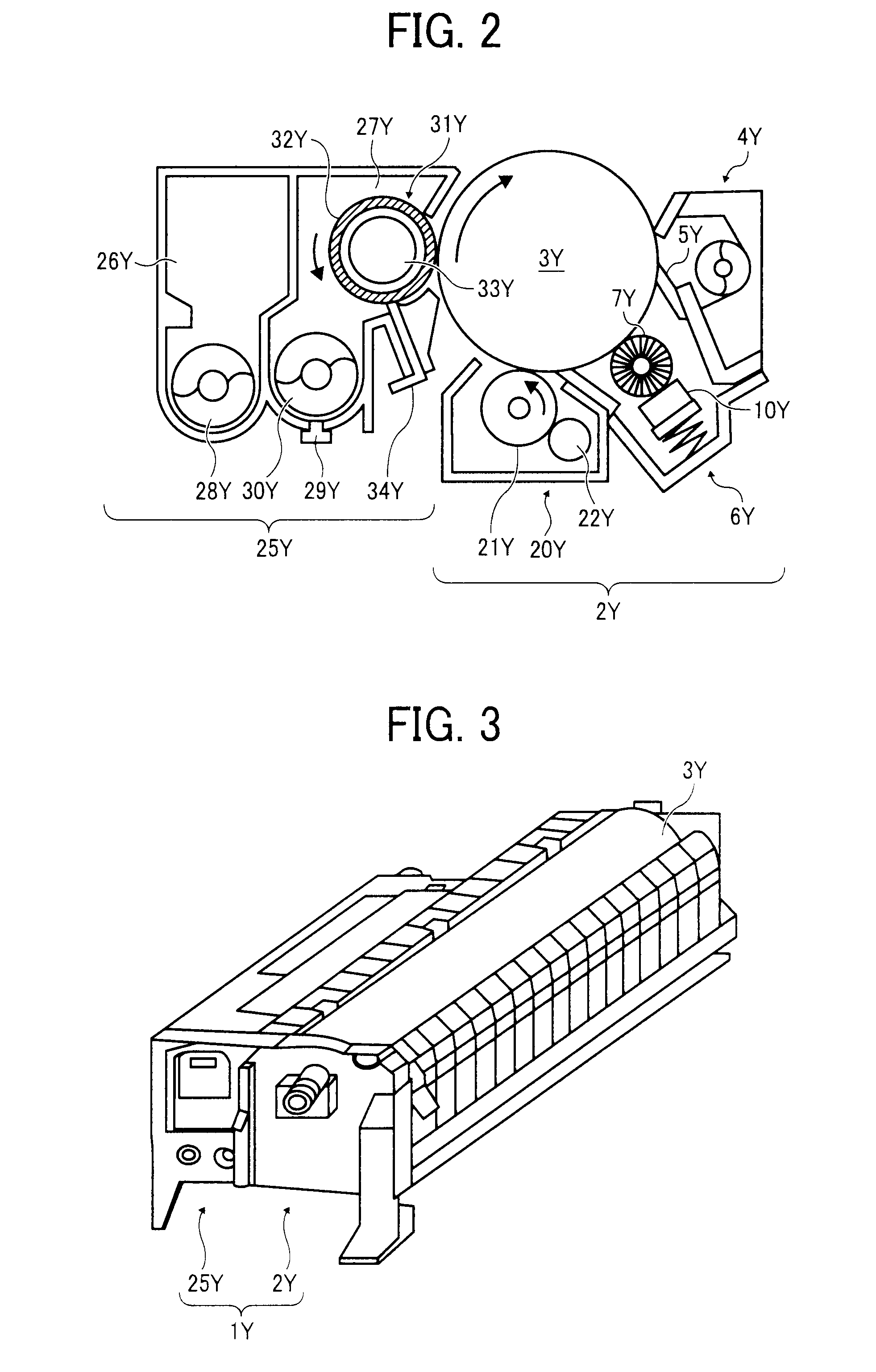
[0132]First, the basic configuration of the printer according to this embodiment will be described. FIG. 1 shows the schematic configuration of the printer according to the embodiment. The printer includes four generating units 1Y, 1C, 1M, and 1K for yellow, magenta, cyan, and black (hereinafter, referred to as Y, C, M, and K), as generating units corresponding to toner image generating units. The generating units use Y, C, M, and K toners of different colors as image forming materials to form images, respectively, but are the same in the other configuration. For example, the generating unit 1Y that generates a Y toner image will be described. As shown in FIG. 2, the generating unit 1Y has a process unit 2Y and a developing unit 25Y. These units as the generating unit 1Y are attached integ...

second embodiment

[0244]Next, the characteristic configuration of the printer according to the second embodiment will be described.

[0245]FIG. 51 is an assembly exploded perspective view partially showing the inner configuration of a solid lubricant applying device 6Y for Y in a printer according to the embodiment. In FIG. 51, the solid lubricant 10Y is fixed to the surface of the holding member 17Y made of C-shape steel, by both-sided tape. The coil spring 19Y presses a back surface of a lubricant fixing surface in the holding member 17Y. The coil spring 19Y biases the solid lubricant 10Y in a direction of an arrow A in the drawings toward the applying brush roller 7Y through the holding member 17Y. The direction of the arrow A is a direction along an orthogonal virtual surface orthogonal to a rotation axis direction of the applying brush roller 7Y and a central direction of the applying brush roller 7Y.

[0246]The solid lubricant 10Y is formed in an elongated block shape to contact almost an entire re...

first example

[0253]FIG. 53 is an assembly exploded perspective view partially showing the inner configuration of a lubricant applying device 6Y for Y in a printer according to the first example. The printer is different from the printer according to the embodiment in that a guide groove is provided as the guide groove GD in which the guide groove is inclined in a direction of an arrow A in the drawings, which is the biasing direction of the coil spring 19Y.

[0254]FIG. 54 is a schematic view showing movement of the holding member 17Y in the guide groove GD of the convex portion 118Y. If the holding member (not shown in the drawings) is biased in the direction of the arrow A in the drawings by the coil spring, the convex portion 118Y that is provided in the holding member moves in the direction of the arrow A in the drawings. In this case, the convex portion 118Y contacts one of the two sidewalls of the guide groove GD. Since the sidewall is inclined in the direction (same direction as the brush ro...


PUM


Abstract

A lubricant applying device includes: a solid lubricant; an applying member that applies lubricant powder scraped off from the solid lubricant to an application target; a holding member that holds the solid lubricant; a biasing unit that biases the holding member to bring the solid lubricant on the holding member into contact with the applying member; and a regulating unit that regulates, when a force of a direction orthogonal to an endless movement direction of the applying member is applied from the applying member to the solid lubricant at a frictional surface therebetween, movement of the solid lubricant and the holding member in the orthogonal direction.

Description

CROSS-REFERENCE TO RELATED APPLICATIONS[0001]The present application claims priority to and incorporates by reference the entire contents of Japanese Patent Application No. 2010-061306 filed in Japan on Mar. 17, 2010, Japanese Patent Application No. 2010-061293 filed in Japan on Mar. 17, 2010, and Japanese Patent Application No. 2010-061297 filed in Japan on Mar. 17, 2010.BACKGROUND OF THE INVENTION[0002]1. Field of the Invention[0003]The present invention relates to a lubricant applying device that applies to an application target lubricant powder that is scraped off from a solid lubricant using an applying member of which the surface endlessly moves, an image forming apparatus using the lubricant applying device, and a process unit. Further, the present invention relates to a solid lubricant that is mounted in the lubricant applying device.[0004]2. Description of the Related Art[0005]In the related art, as this kind of lubricant applying device, there is known a lubricant applying...

Claims


Application Information

Patent Timeline
Patent Type & Authority Applications(United States)
IPC IPC(8): G03G21/00
CPCG03G21/007G03G21/0094G03G2221/1606
Inventor KOJIMA, TAKESHIKAWASUMI, MASANORITANAKA, SHUJIKAYAHARA, SHINSUGANUMA, TAKUYASUGIYAMA, HIROYUKIISHIKURA, YUJI
Owner RICOH KK
Why Eureka
Try Eureka