Charging connector

a charging connector and connector technology, applied in the direction of charging stations, transportation and packaging, coupling device connections, etc., can solve the problems of large amount of foreign matter accumulating in the cavity, the charging connector may be dropped, and the foreign matter cannot be prevented from entering the cavity between the fitting and the terminal accommodating portion, etc., to achieve the effect of preventing damage to the front wall, facilitating formation, and simplifying the construction of the holder

Inactive Publication Date: 2011-09-22
SUMITOMO WIRING SYST LTD
View PDF9 Cites 7 Cited by
  • Summary
  • Abstract
  • Description
  • Claims
  • Application Information

AI Technical Summary

Benefits of technology

[0010]According to this construction, the resilient member closely contacts the vehicle-side terminal over substantially the entire circumference when the vehicle-side terminal is connected to the terminal fitting. Thus, foreign matter deposited on a surface of the vehicle-side terminal can be removed. Further, the resilient member at the front wall of the cavity absorbs the impact if the charging connector is dropped by mistake and thus prevents damage to the front wall of the in addition to restricting the entry of foreign matter into the cavity.
[0011]The front wall of the cavity may be formed integrally or unitarily to the terminal accommodating portion by co-molding or two-color molding. Thus, the front wall can be formed more easily as compared with the case where the front wall is formed as a separate member and is mounted separately on the terminal accommodating portion.
[0012]A contact portion is formed on the front wall of the cavity and extends substantially in an inserting direction of the vehicle-side terminal. The contact portion is held in close surface contact with the vehicle-side terminal to restrict entry of foreign matter due to an increased contact area.
[0013]The front wall of the cavity may include a cavity inner wall defining an inner wall of the cavity. The resilient member is arranged on the front side of the cavity inner wall and a holder holds the resilient member between the cavity inner wall portion and the holder. The resilient member between the cavity inner wall and the holder restricts detachment of the resilient member due to insertion and withdrawal of the vehicle-side terminal.
[0014]The holder may be press-fit onto the cavity inner wall. The press-fitting of the holder onto the cavity inner wall simplifies the construction of holder.

Problems solved by technology

The above-described charging connector can prevent foreign matter from entering the fitting, but cannot prevent foreign matter from entering between the fitting and the terminal accommodating portion, i.e. the cavity.
As a result, a large amount of foreign matter accumulates in the cavity by repeatedly inserting and withdrawing the vehicle-side terminal.
Further, the charging connector may be dropped by mistake and can be damaged by a protruding object present at a falling point.
More particularly, a front part of the terminal accommodating portion, i.e. a front wall of the cavity, may be damaged by colliding with the protruding object if the charging connector is dropped.

Method used


Image

  • Charging connector
  • Charging connector
  • Charging connector

Examples


first embodiment

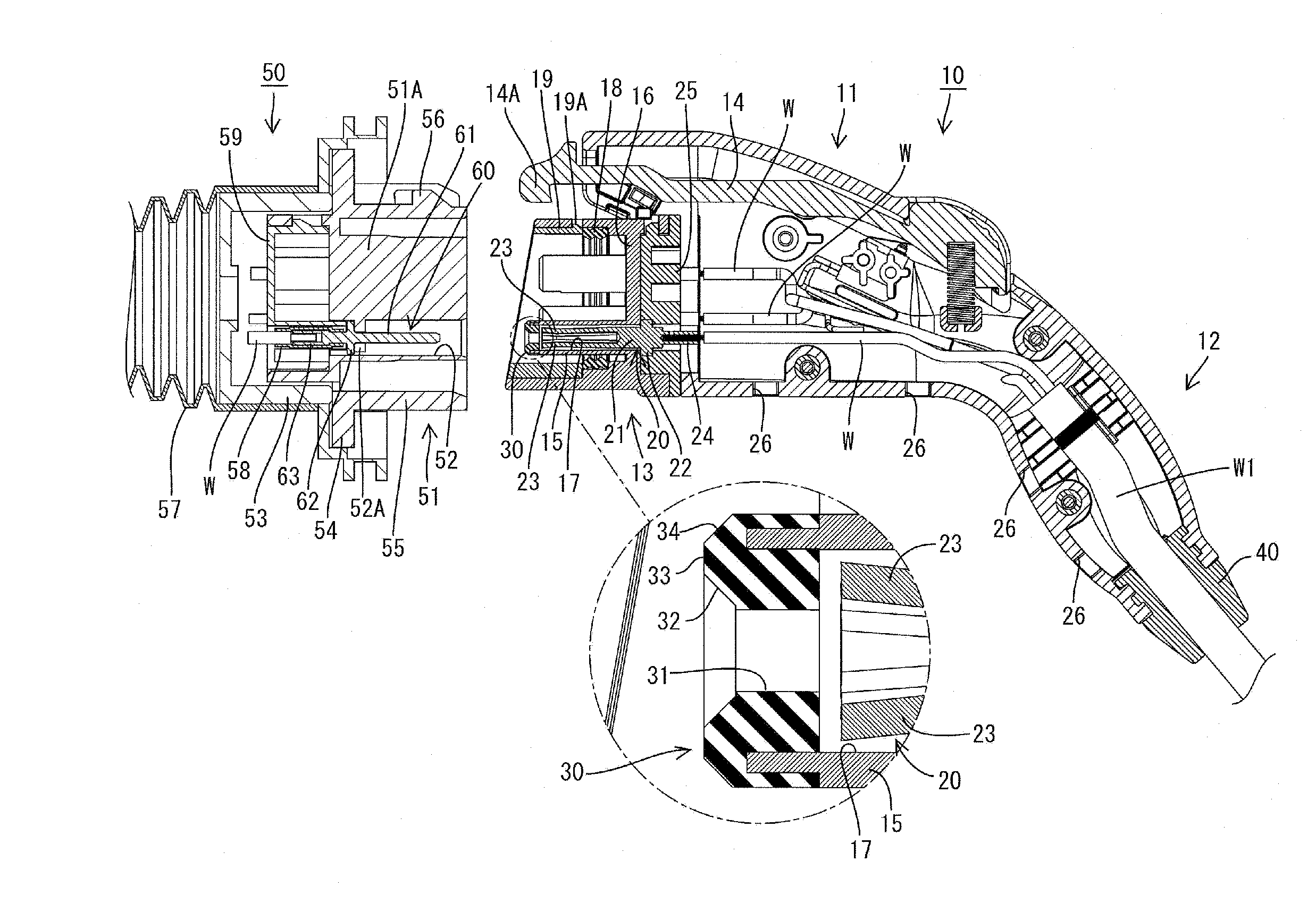
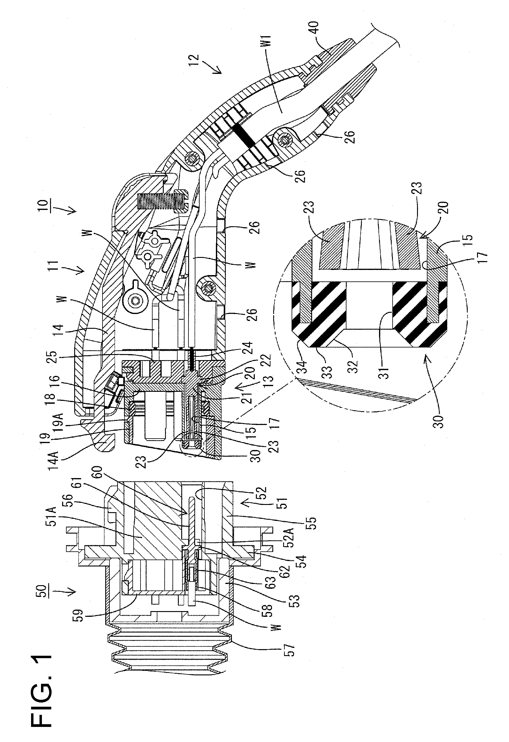
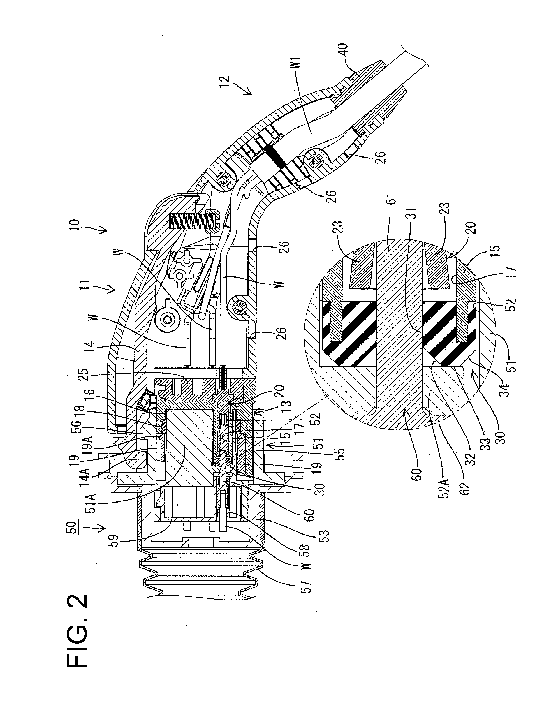
[0027]the invention is described with reference to FIGS. 1 and 2. A charging connector 10 of this embodiment is connectable with a vehicle-side connector 50. In the following description a connection direction of the charging connector 10 with the vehicle-side connector 50 is referred to as a front end or a forward direction. The charging connector 10 is substantially gun-shaped and has a main body 11 constituting a front portion and a grip 12 extending obliquely down from a rear portion of the main body 11, as shown in FIG. 1. The main body 11 and the grip 12 both are molded unitarily of a substantially rigid synthetic resin. A substantially cylindrical receptacle 13 projects forward on the front of the main body 11. A lever 14 is accommodated at an upper side of the interior of the main body 11, and a front end thereof is exposed from the front of the upper surface of the connector main body 11.

[0028]The receptacle 13 is formed as a separate member from the main body 11, and fixed...

second embodiment

[0047]the invention is described with reference to FIG. 3. The second embodiment is obtained by partly changing the construction of the front wall of the cavity 17 of the first embodiment. Other constructions, functions and effects are the same or similar and are not described again. Further, the identical or similar constructions as in the first embodiment are identified by the same reference numerals. A front wall of a cavity 17 in this embodiment comprises a resilient member 70 as shown in FIG. 3. The resilient member 70 is formed integrally with a terminal accommodating portion 15 by co-molding or two-color molding as in the first embodiment and constitutes a part of the terminal accommodating portion 15.

[0048]An insertion hole 71 penetrates a central part of the resilient member 70 and can receive a male-side main portion 61 of a vehicle-side terminal 60. At least one substantially ring-shaped sealing projection 72 is formed to project radially inwardly at the front end of the ...

fourth embodiment

[0056]the invention is described with reference to FIG. 5. The fourth embodiment is obtained by partly changing a method for fixing the holding cap 81 and the front wall portion 82A in the third embodiment. Other constructions, functions and effects are not described because they are the same or similar to those described above. Rather, the similar or substantially same constructions as in the third embodiment are identified by the same reference numerals.

[0057]An internal thread is formed in the inner circumferential surface of an outer peripheral flange 81B, an external thread is formed on the outer circumferential surface of a base 82C, and a holding cap 81 is threadedly mounted on a front wall 82A by fitting the base 82C into the inner side of the outer peripheral flange 81B and tightening the holding cap 81. Therefore, the holding cap 81 can be mounted firmly on the front wall 82A.

[0058]The invention is not limited to the above described and illustrated embodiments. For example...


PUM


Abstract

A charging connector (10) is provided for connection to a vehicle-side connector (50) in a vehicle. The charging connector (10) has terminal fittings (20) to be electrically conductively connected to vehicle-side terminals (60) in the vehicle-side connector (50), and terminal accommodating portions (15) internally formed with cavities (17) for accommodating the terminal fittings (20). A front wall of each cavity (17) includes a resilient member (30) that allows the insertion of the vehicle-side terminal (60) into the cavity (17) while being held in close contact with the vehicle-side terminal (60) over the entire circumference.

Description

BACKGROUND OF THE INVENTION[0001]1. Field of the Invention[0002]The invention relates to a charging connector connectable to a vehicle-side connector in a vehicle.[0003]2. Description of the Related Art[0004]U.S. Pat. No. 5,921,803 discloses a charging with a terminal accommodating portion integrally formed with a cavity for accommodating a terminal fitting. The terminal fitting includes a cylindrical fitting for receiving a pin-shaped vehicle-side terminal of a vehicle-side connector. A circumferential groove is formed in the inner circumferential surface of the fitting and an O-ring is mounted in the circumferential groove. The O-ring closely contacts the vehicle-side terminal over the entire circumference to wipe off foreign matter, such as muddy water deposits, on a surface of the vehicle-side terminal and prevents the foreign matter from entering the fitting.[0005]The charging connector is used outdoors. Thus, a muddy water test is conducted in which the charging connector is i...

Claims


Application Information

Patent Timeline
Patent Type & Authority Applications(United States)
IPC IPC(8): H01R13/40
CPCB60L11/1818B60L2230/12H01R13/111H01R13/504H01R13/5045H01R13/512B60L2270/34H01R2201/26Y02T10/7005Y02T10/7088Y02T90/121Y02T90/14B60L2270/32H01R13/521B60L53/16B60L53/18Y02T10/70Y02T10/7072Y02T90/12
Inventor TAKADA, AKINORI
Owner SUMITOMO WIRING SYST LTD
Why Eureka
Try Eureka