Plastics molding system and optical element formed by the same

a technology of plastic molding and optical elements, which is applied in the field of plastic molding systems and optical elements formed by plastic molding systems, can solve the problems of long cooling time, molds cannot be used, and the need to take long cooling time, etc., and achieve the effect of high precision shap

Inactive Publication Date: 2011-09-29
CANON KK
View PDF1 Cites 5 Cited by
  • Summary
  • Abstract
  • Description
  • Claims
  • Application Information

AI Technical Summary

Benefits of technology

[0011]The present invention is directed to a plastics molding system useful for obtaining molded products with optical characteristics of small refractive index distribution

Problems solved by technology

However, according to a molding using such processing, it is necessary to take long cooling time when molding thick products or high precision products used, for example, in optical systems such as plastic lenses, prisms, and mirrors.
While the resin is cured, which takes long time, the mold cannot be used.
Thus, the injection molding machine cannot be used for the injection of the next resin while the injected resin is being cured.
For this reason, the usage ratio of the injection molding machine is not good and productivity is not increased.
Since longer cooling time is necessary if the mold cooling speed is decreased and higher mold tempe

Method used


Image

  • Plastics molding system and optical element formed by the same
  • Plastics molding system and optical element formed by the same
  • Plastics molding system and optical element formed by the same

Examples


Embodiment Construction

[0023]Various exemplary embodiments, features, and aspects of the invention will be described in detail below with reference to the drawings.

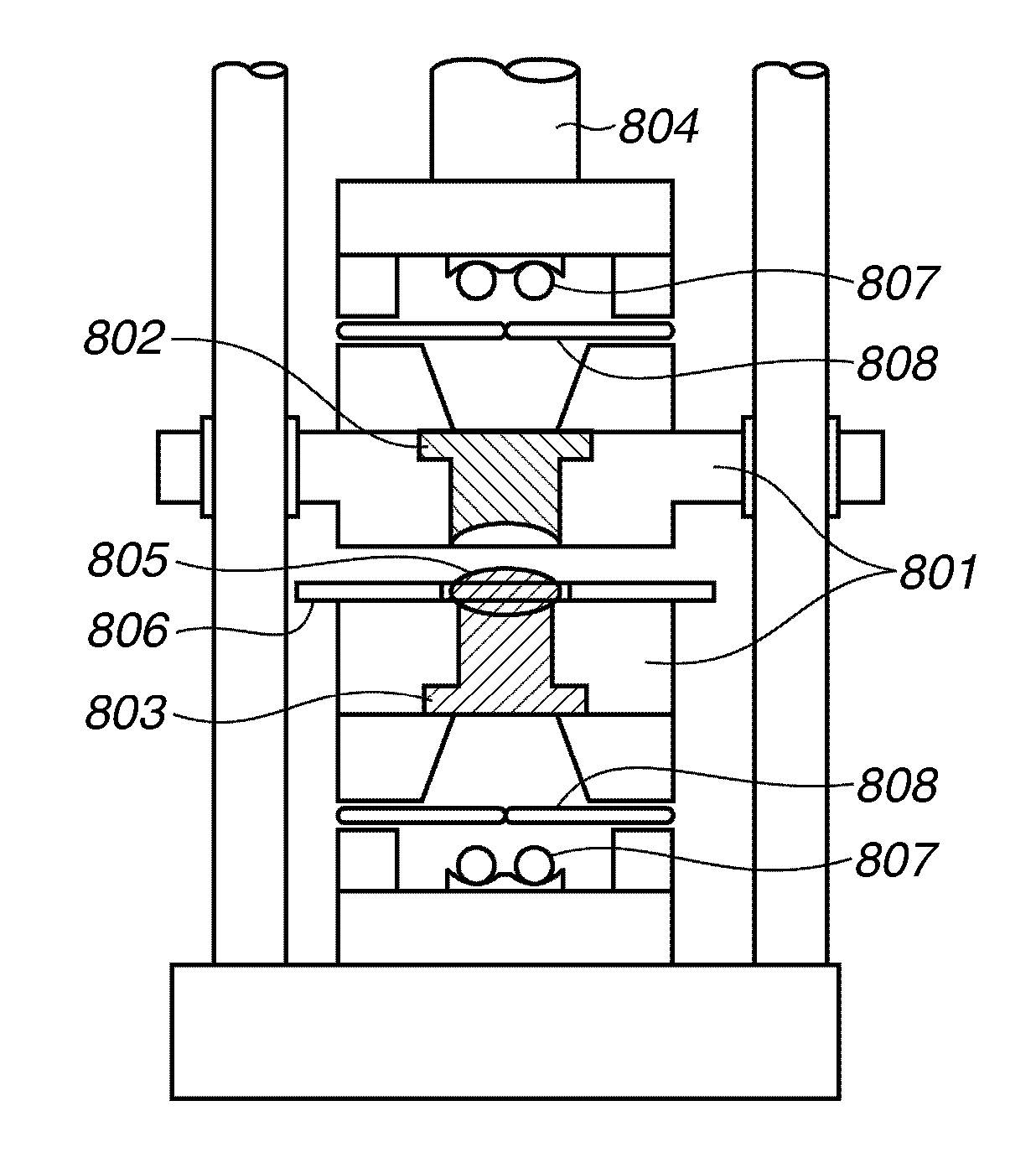
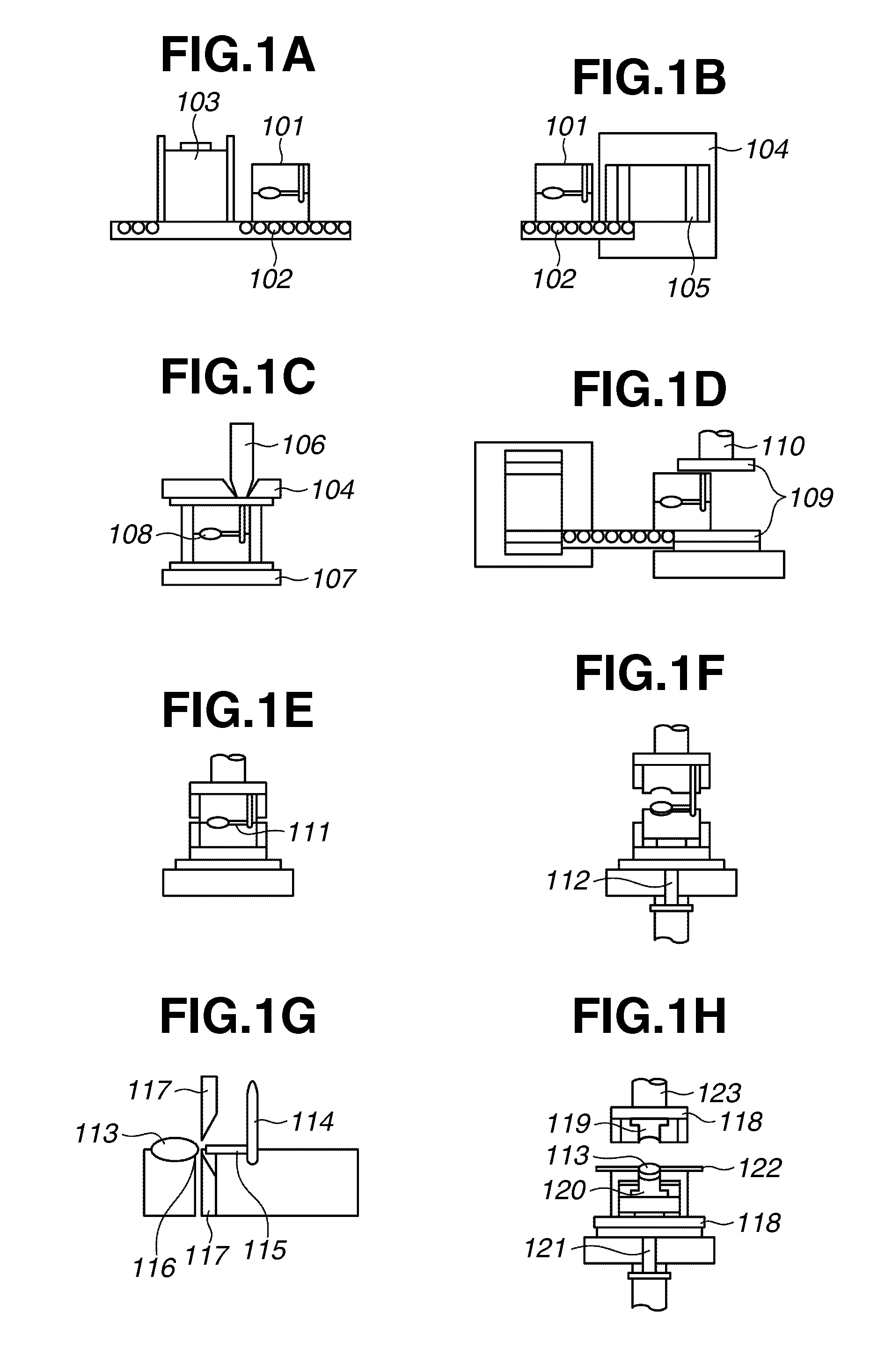
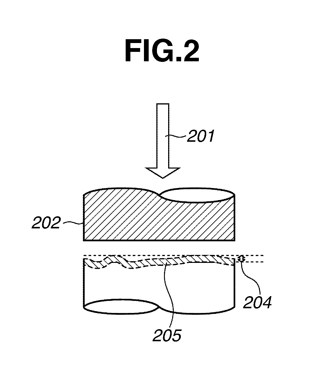
[0024]A rotary molding system including a heating unit, a molten resin supply unit, a first pressing-cooling unit, and a molded product take-out unit takes a considerable amount of time in applying pressure to the mold and cooling the mold while controlling its temperature and requires a great number of molds in reducing the takt time. Thus, according to the molding method for forming plastic molded products and the plastics molding system of the present invention, a mold having a shape similar to a desired shape but with a lower surface precision level is used in the molding in the above-described process where a considerable number of molds are required. When a molded product is obtained, only the outer surface of the molded products is remolded using a high-precision mold with a desired shape.

[0025]To be more precise, the above-described sys...


PUM

PropertyMeasurementUnit
Glass transition temperatureaaaaaaaaaa
Temperatureaaaaaaaaaa
Moldableaaaaaaaaaa

Abstract

A molding method of a plastic molded product includes preparing at least one mold including a high-precision surface; preparing a plurality of molds having a low-precision surface; sequentially supplying molten resin to one of the plurality of molds having low-precision surface; sequentially cooling, for a predetermined length of time, the molds supplied with the molten resin while applying pressure, taking out a molded member from the cooled mold, setting the molded member which has been taken out in the mold having the high-precision surface, and melting only a surface of the molded member while pressing the high-precision surface against the surface to form a plastic molded product.

Description

BACKGROUND OF THE INVENTION[0001]1. Field of the Invention[0002]The present invention relates to a plastics molding system and an optical element formed by the plastics molding system. More particularly, the present invention relates to a plastics injection molding system using a plurality of molds, which is so-called a rotary molding system. According to the rotary molding system, the site where the molds are cooled is different from where the injection filling is performed.[0003]2. Description of the Related Art[0004]When a plastic product is formed by injection molding, normally, after a mold is set on an injection molding machine, a heated and molten resin is injected into the mold. When the resin is cured by cooling, the cured resin is taken out from the mold. Then, the next molten resin is injected into the empty mold. This processing is repeated.[0005]However, according to a molding using such processing, it is necessary to take long cooling time when molding thick products o...

Claims


Application Information

Patent Timeline
IPC IPC(8): B29C45/72
CPCB29C45/0055B29L2011/0016B29C45/7207B29C45/561
Inventor OGANE, MASANOBUTAKATA, ATSUSHI
Owner CANON KK
Why Eureka
Try Eureka