Method of manufacturing glass melt, method of manufacturing molded glass materials, and method of manufacturing optical elements

A technology of molten glass and manufacturing method, which is applied in glass forming, glass pressing, glass manufacturing equipment, etc. It can solve the problems of affecting the liquid level measurement results, the reflection position deviates from the light receiver, and the liquid level measurement cannot be carried out. The effect of stable outflow and easy temperature adjustment

Inactive Publication Date: 2007-06-20
HOYA CORP
View PDF3 Cites 0 Cited by
  • Summary
  • Abstract
  • Description
  • Claims
  • Application Information

AI Technical Summary

Problems solved by technology

The deformation of the clarification tank will affect the position accuracy of the laser emitter and light receiver installed on the side wall of the clarification tank, as a result, it will affect the measurement results of the liquid level and cause measurement errors
[0006] In addition, in the method disclosed in Patent Document 1, when the height of the molten glass surface changes greatly, the reflected position of the light from the laser emitter deviates from the light receiver, causing the problem that liquid level measurement cannot be performed.

Method used


Image

  • Method of manufacturing glass melt, method of manufacturing molded glass materials, and method of manufacturing optical elements

Examples


Embodiment 1

[0073] Hereinafter, embodiments will be described in detail with reference to the drawings.

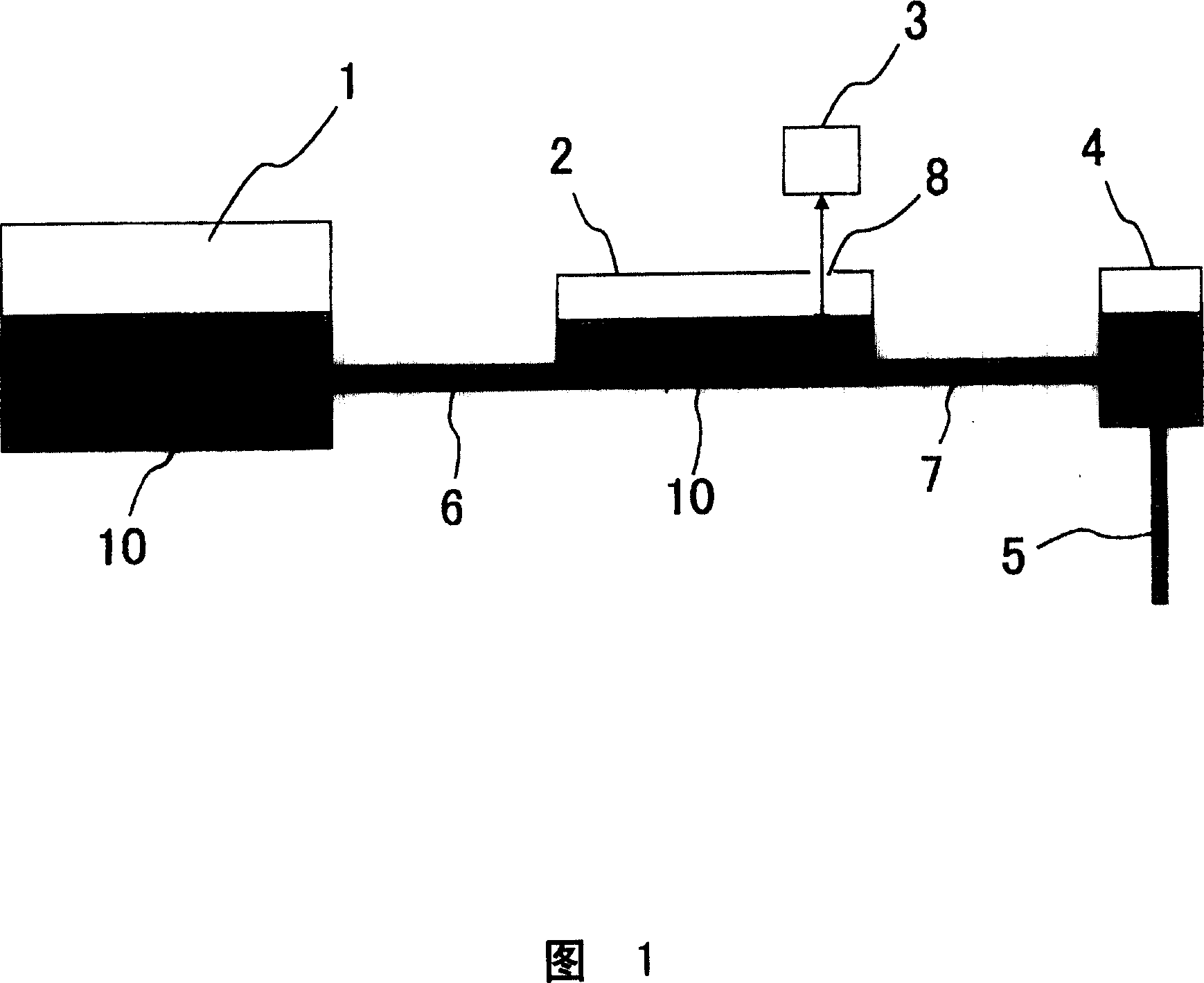
[0074] FIG. 1 is a schematic cross-sectional view of a glass melting apparatus used in this example. There is a raw material inlet (not shown) in the upper part of the melting tank 1, and the glass raw material is put in there. The input raw material becomes molten glass 10 after being heated and melted in the melting tank, and flows into the clarification tank 2 through the connecting pipe 6 .

[0075] The upper part of the clarification tank 2 is provided with the opening part 8 which extracts the gas which generate|occur|produces from glass by clarification. Above the opening 8, a laser ranging sensor 3 including a light source for emitting laser light and a light receiving unit for receiving reflected laser light from the liquid surface for monitoring the liquid level of the molten glass is fixed at a place separated from the clarification tank 2 .

[0076] The laser light emitt...

Embodiment 2

[0084] The molten glass produced by the method of Example 1 was poured into the mold from the outflow pipe at a constant flow rate to produce a sheet glass made of optical glass containing rare earth oxides. This sheet glass is annealed and cut into a predetermined shape to form slices.

[0085] Next, after reheating the chips, they are press-formed with a press-forming die to obtain a lens-shaped molded product. Grinding and lapping are performed on the molded product to form a lens. The optical characteristics of the obtained lens were desired values.

Embodiment 3

[0087] The molten glass produced by the method of Example 1 flowed out from the outflow pipe, was supplied to the forming surface of the lower mold, and was pressed using the upper mold facing the lower mold to form a lens shape. Grinding and lapping are performed on this molded article to obtain a lens made of glass containing rare earth oxides. The optical characteristics of the obtained lens were desired values.


PUM


Abstract

In the method for manufacturing the molten glass, the melting of glass or the discharge of the molten glass is carried out while monitoring the height of the liquid level of the molten glass in the vessel having a cover on the upper part. The liquid level is monitored by making monitoring light almost vertically incident on the molten glass liquid surface from the outside through an opening part provided on the cover, exiting the light reflected from the liquid surface through the opening part and detecting the light outside the vessel. The method for manufacturing the glass molding includes a process for allowing the molten glass manufactured by the above method to flow out and molding the flow-out glass. The subject method for manufacturing an optical element includes a process for manufacturing the optical element by machining the glass molding manufactured by the above method. The optical element is obtained by heating a preform for precise press molding which is manufactured by the above method and precisely press-molding it.

Description

technical field [0001] The present invention relates to a method for melting glass, a method for producing a glass molded body from molten glass, and a method for producing an optical element. Background technique [0002] When adding glass raw materials to a container of molten glass or flowing molten glass from the container, it is necessary to monitor the liquid level of the molten glass accumulated in the container. As a method of monitoring the liquid level, for example, there is a method described in FIG. 3 of Japanese Patent Publication No. 57-57413 (Patent Document 1). In this method, the light emitted from a laser emitter installed on the side wall of a clarification tank is reflected by the liquid surface of molten glass, and the light receiver installed on the side wall of the opposite clarification tank detects the reflected light, thereby measuring the liquid level. This method has the feature of measuring the glass level without contacting the molten glass. ...

Claims


Application Information

Patent Timeline
Patent Type & Authority Patents(China)
IPC IPC(8): C03B5/16C03B11/00G01F23/28C03B5/24C03B7/12G01F23/292
CPCC03B5/245C03B7/12G01F23/292
Inventor 加藤秀次铃木恒司下西司
Owner HOYA CORP
Why Eureka
Try Eureka