Device storage apparatus for railway vehicle

a storage apparatus and railway vehicle technology, applied in the direction of electric propulsion mounting, locomotives, furniture parts, etc., can solve the problems of unstable operation of one hand to move the tray with a substantial weight, complex lock structure, and easy shaking of the railcar during driving, so as to achieve easy and stable operation, simple configuration, and easy to move the tray

Active Publication Date: 2011-09-29
KAWASAKI RAILCAR MFG CO LTD
View PDF8 Cites 25 Cited by
  • Summary
  • Abstract
  • Description
  • Claims
  • Application Information

AI Technical Summary

Benefits of technology

[0009]In accordance with this configuration, by pulling out the tray in a forward direction while pushing down the operation member provided at the tray with an operator's hand, the device mounted on the tray can be easily pulled out from the storage case. To be specific, when the operator pushes down the operation member, the rear end portion of the lever moves up according to down movement of the front end portion of the lever, and the engagement portion disengages from the recess, thereby allowing the tra...

Problems solved by technology

The railcar tends to shake during driving.
In addition, the operation for moving the ...

Method used


Image

  • Device storage apparatus for railway vehicle
  • Device storage apparatus for railway vehicle
  • Device storage apparatus for railway vehicle

Examples


Embodiment Construction

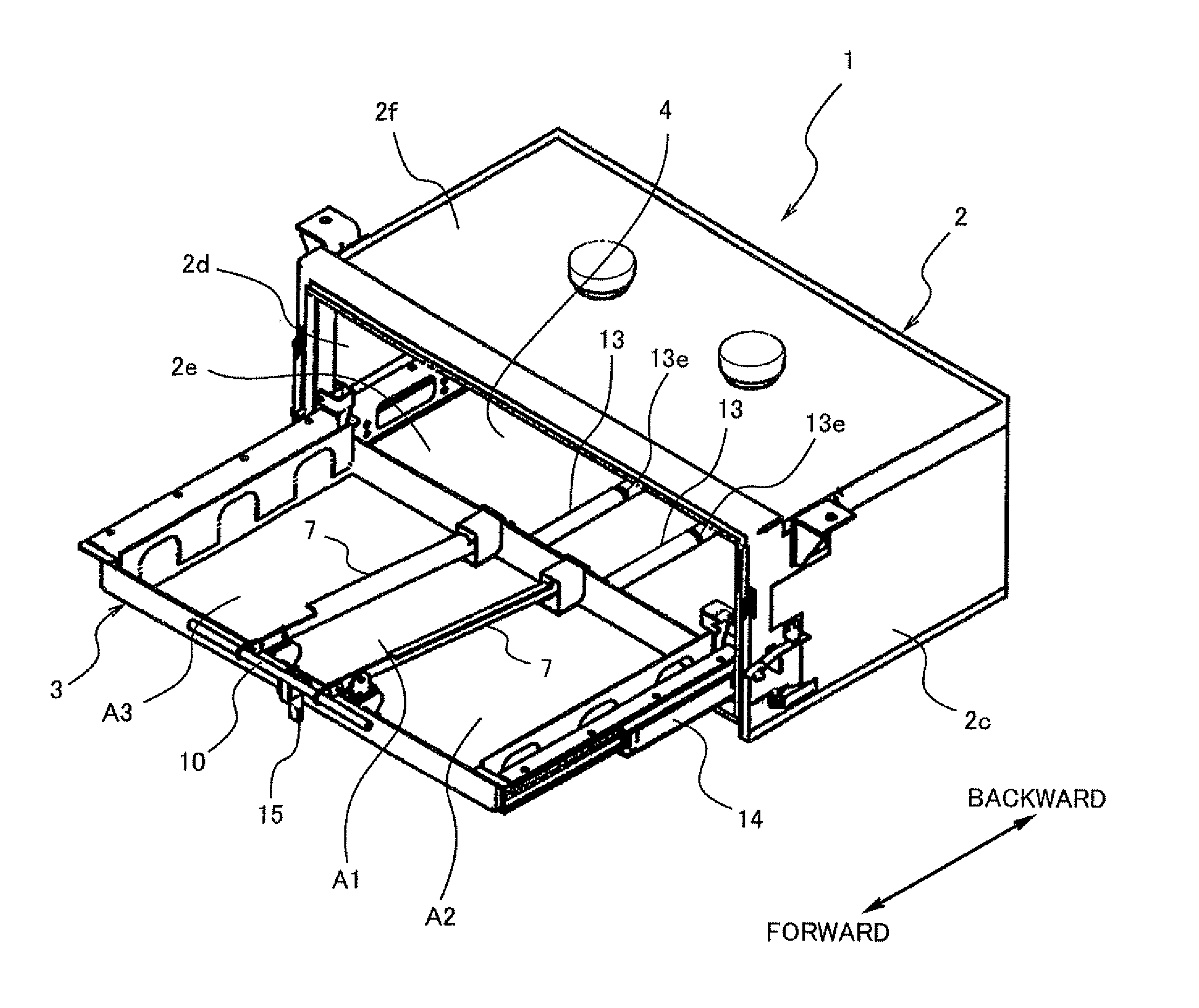
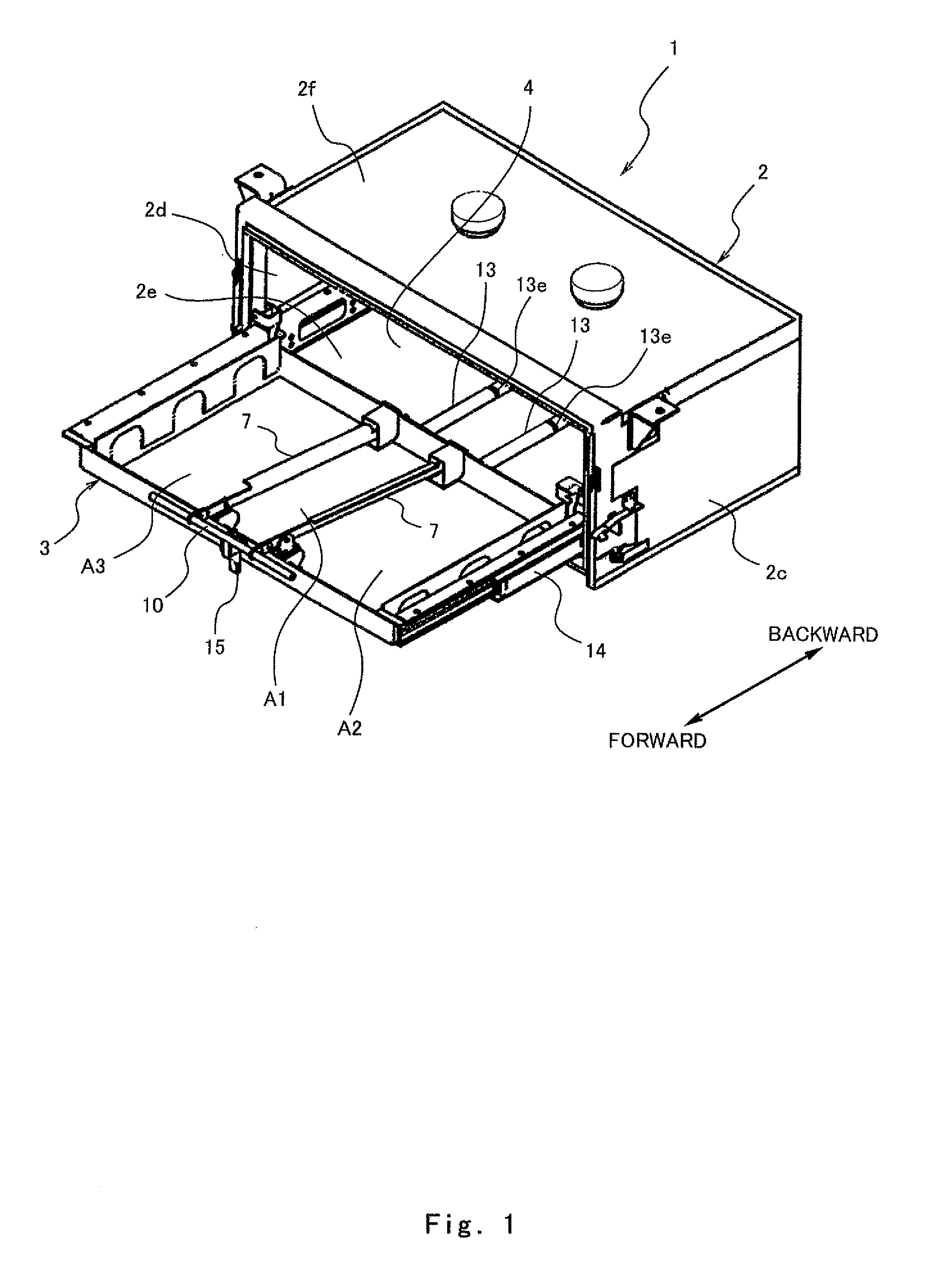
[0020]Hereinafter, an embodiment of the present invention will be described with reference to the drawings. In this embodiment, a battery storage apparatus will be described, but the present invention is applicable to storage apparatuses for various devices as well as batteries. In particular, the present invention is useful in a case where the device is pulled out, inspected and maintained. Hereinafter, it is supposed that the battery storage apparatus is mounted under a floor of a railcar, but may be positioned anywhere else. The stated directions are such that a side of the battery storage apparatus where an opening is formed, i.e., a direction in which the tray is pulled out, is forward.

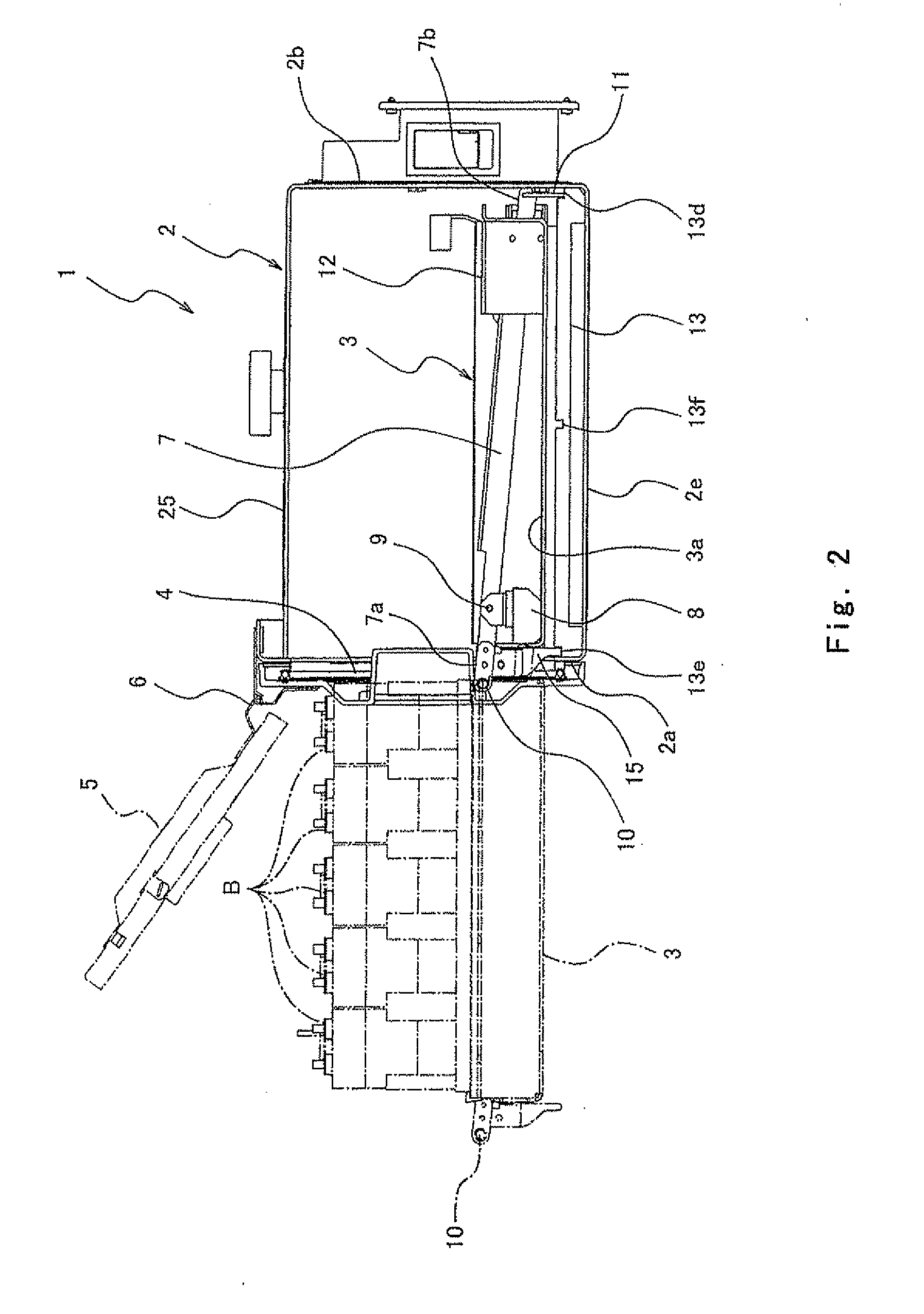
[0021]FIG. 1 is a perspective view showing a state where a battery storage apparatus 1 according to an embodiment of the present invention, is pulled out. FIG. 2 is a side cross-sectional view (one-dotted line indicates a pulled-out state) in a storage state of the battery storage apparatus 1 of ...


PUM


Abstract

An apparatus for storing a device for a railway vehicle, comprises a storage case having an opening at a front side, a tray accommodated into the storage case, the tray being movable forward and backward with the device mounted thereon, a lever disposed at an upper side of the tray to extend along a forward and backward direction, the lever being vertically pivotable around a pivot forward relative to a center of the tray in the forward and backward direction, an operation member coupled to a front end portion of the lever and disposed at a front side of the tray, an engagement portion provided at a rear end portion of the lever and protruding downward outside the tray, and a recess provided in the storage case, the engagement portion being fitted into the recess from above.

Description

CROSS-REFERENCE TO RELATED APPLICATION[0001]This application claims priority to and the benefit of Japanese Patent Application No. 2010-033312 filed on Feb. 18, 2010, the entire disclosure of which is incorporated herein by reference.BACKGROUND OF THE INVENTION[0002]1. Field of the Invention[0003]The present invention relates to a device storage apparatus for a railway vehicle.[0004]2. Description of the Related Art[0005]Typically, in a railcar, various devices such as a controller and electric devices are mounted into a storage apparatus and arranged under a floor of a railcar or inside the railcar. During inspection or maintenance, a cover of the storage apparatus is opened, states of the devices in the storage apparatus are checked, and then maintenance of them is carried out if necessary. For example, batteries which are one example of the devices, are mounted to the railcar as a backup electric power supply in the case of electric power failure. To this end, it is necessary to ...

Claims


Application Information

Patent Timeline
IPC IPC(8): A47B81/00A47B96/00
CPCB61C17/00
Inventor KATAOKA, SHINTAKAGI, KUNIHIKOKITAGAWA, YUTAKA
Owner KAWASAKI RAILCAR MFG CO LTD
Why Eureka
Try Eureka