Modulated supply stage with feedback to switched supply

a moduled supply and switching supply technology, applied in the direction of electric variable regulation, process and machine control, instruments, etc., can solve the problems of no net gain in efficiency, difficulty in application of these techniques, and difficulty in particular, so as to maximize the current flowing and minimize the current flowing

Inactive Publication Date: 2011-09-29
SNAPTRACK
View PDF12 Cites 72 Cited by
  • Summary
  • Abstract
  • Description
  • Claims
  • Application Information

AI Technical Summary

Benefits of technology

[0053]The controlling the current in the combining means to maximize the current flowing in the combining means and thereby minimize the current flowing in the correction means may include determining the current flow in the inductor and modifying coefficients of a differentiator in dependence thereon.

Problems solved by technology

However, it is also known that the application of these techniques presents considerable difficulties due to the large powers and bandwidths involved.
These difficulties become particularly formidable when applied to portable wireless terminals where the number of discrete components must be minimised and large dimensioned magnetics must be avoided.
However, this would simply change power wasted in the power amplifier with that wasted in the linear regulator, resulting in no net gain in efficiency.
However a problem arises in that there must be sufficient range in the linear regulator to allow for the peaks in the switched mode error, which can be considerably larger than the root mean square (RMS) error.
This results in a large standing dissipation in the LDO.
A potential problem with the architecture of FIG. 1 is that the transformer 110 has to have a high self-inductance to prevent shunting of the correction current through the unwanted inductance of the transformer.
This means that large ferrite cores must typically be used.
Whilst this is acceptable for wireless infrastructure implementations, this presents particular difficulties for portable handset implementations or any implementation where size restrictions may apply.
For low frequency outputs (frequencies much less than the switching frequencies), this arrangement will be able to perform tracking, but the circuit may provide poor tracking at high frequency.
Also, the high output impedance may result in instability of the load.

Method used


Image

  • Modulated supply stage with feedback to switched supply
  • Modulated supply stage with feedback to switched supply
  • Modulated supply stage with feedback to switched supply

Examples


Embodiment Construction

[0064]The invention will now be described by way of example with reference to its application in various embodiments. One skilled in the art will appreciate that the invention is not limited in its scope to the specifics of implementation details of any particular embodiment.

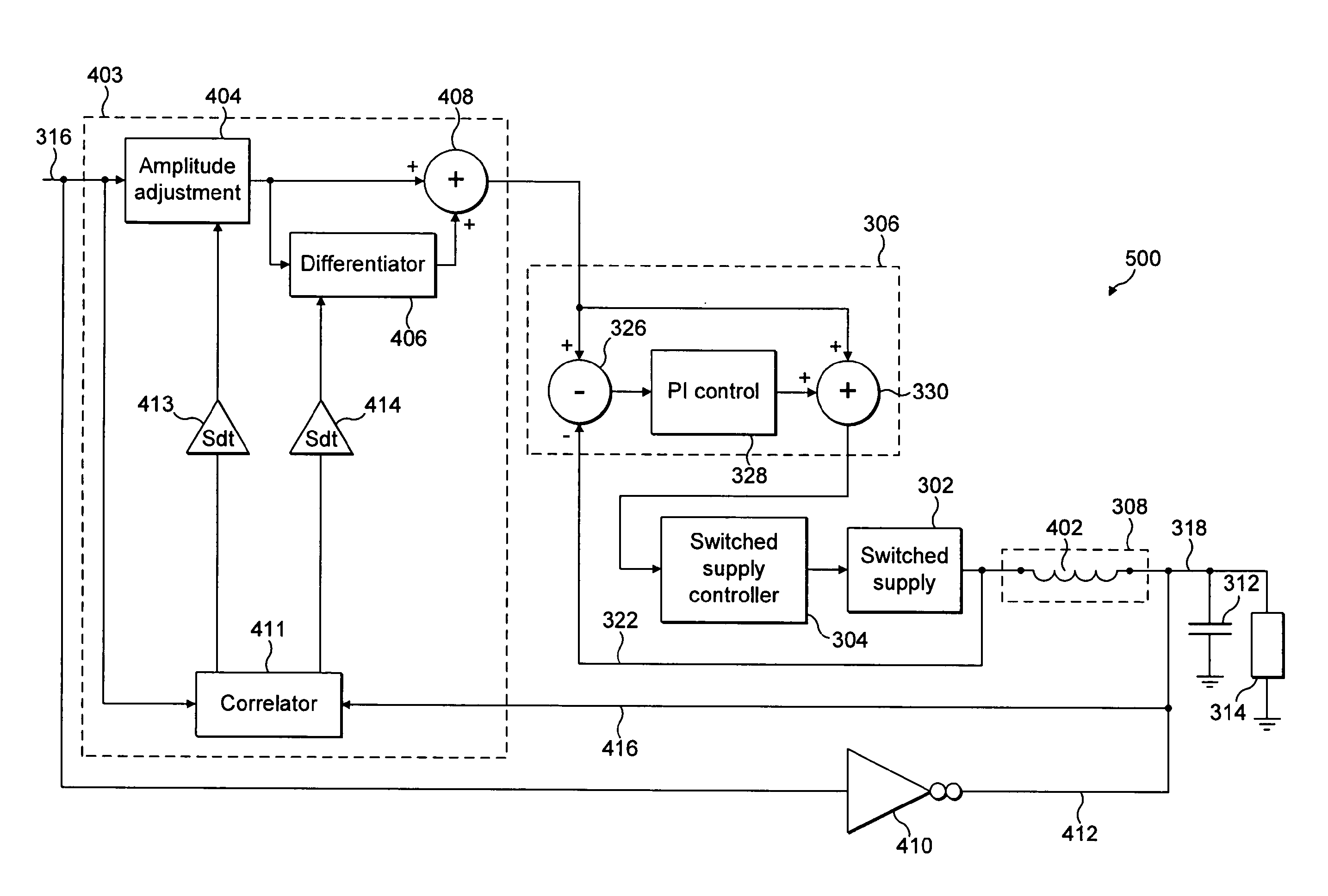
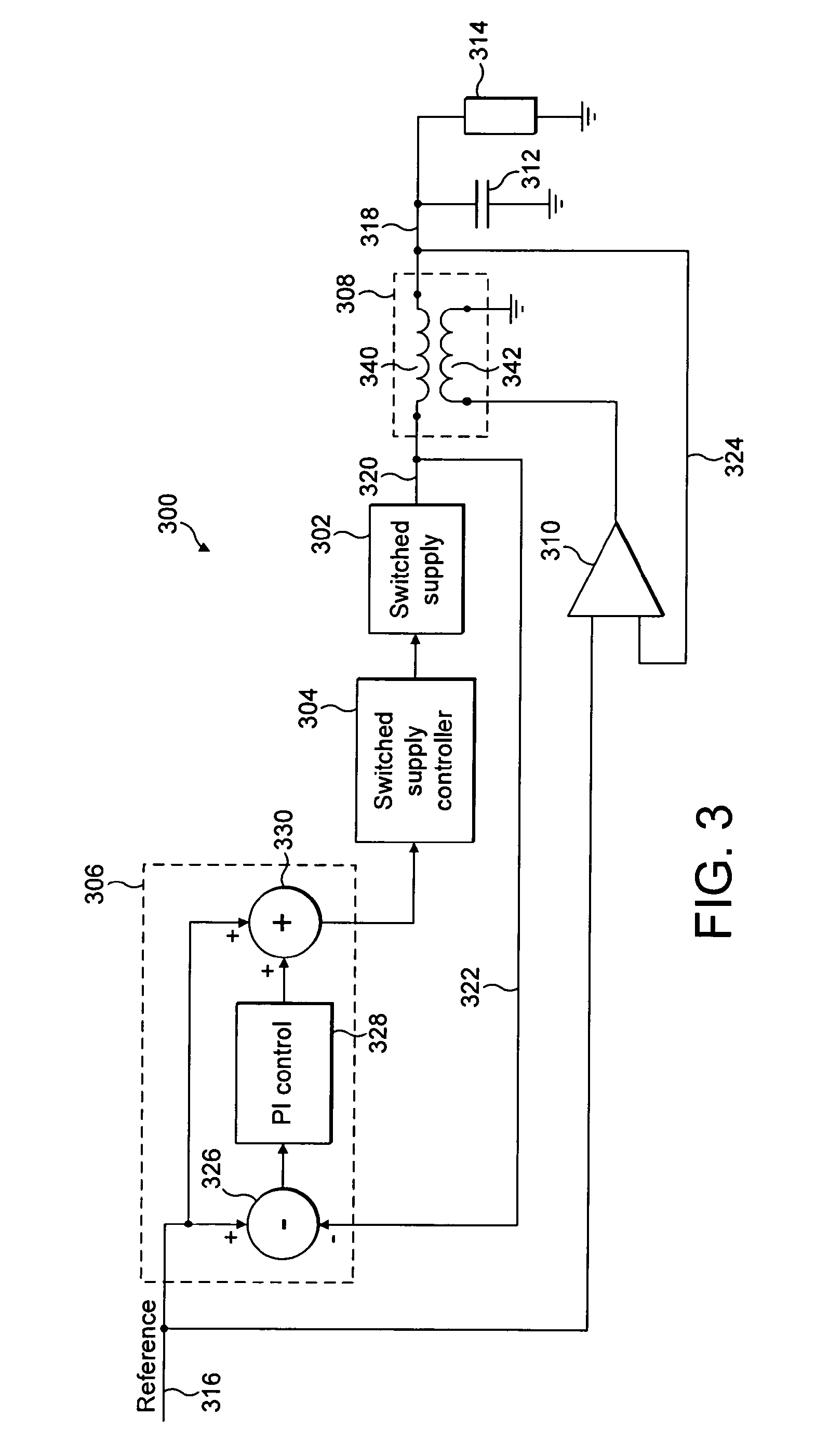
[0065]The broad principle in accordance with the invention is to provide an additional feedback path. The feedback path provides an input to the switched supply.

[0066]The provision of the feedback path is in accordance with one of two broad embodiments. In a first broad embodiment the feedback path originates from the output of the switched supply, i.e. the output of a coarse path. In a second broad embodiment the feedback path originates from the output of the correction path. Thus the switched supply stage is provided an input derived from an input to the combiner stage for combining the switched supply with the correction signal. This feedback reduces errors at low frequencies, and allows the bandwidth of the...


PUM


Abstract

There is disclosed a voltage supply stage comprising: a selection means for selecting one of a plurality of power supply voltages in dependance on a reference signal representing a desired power supply voltage; a combining means for combining the selected power supply voltage with a correction signal to generate an adjusted power supply voltage; and an adjusting means adapted to generate the correction signal in dependence on the reference signal and the adjusted power supply voltage, wherein the selection means is arranged to select the one of the plurality of supply voltages further in dependence on a signal derived from one of the inputs to the combining means.

Description

BACKGROUND TO THE INVENTION[0001]1. Field of the Invention[0002]The present invention relates to a modulated supply stage, and particularly to such a stage in which a feedback loop is connected to provide an input to control selection of a low frequency switched supply. The feedback may be provided from the output of the low frequency switched supply stage or from the output of a high frequency correction stage.[0003]2. Description of the Related Prior Art[0004]It is known by those skilled in the art that envelope tracking (ET) and envelope elimination and restoration (EER) can give large improvements in efficiencies of power amplifier operation, particularly with signals such as orthogonal frequency-division multiplexing (OFDM) which have large crest factors. However, it is also known that the application of these techniques presents considerable difficulties due to the large powers and bandwidths involved. These difficulties become particularly formidable when applied to portable ...

Claims


Application Information

Patent Timeline
Patent Type & Authority Applications(United States)
IPC IPC(8): G05F1/10
CPCH02J4/00H03F1/0227G05F1/563H03F1/0222H02M3/04H03F3/21
Inventor WILSON, MARTIN PAUL
Owner SNAPTRACK
Why Eureka
Try Eureka