Head-mounted type display device

Active Publication Date: 2011-09-29
OLYMPUS CORP
View PDF17 Cites 44 Cited by
  • Summary
  • Abstract
  • Description
  • Claims
  • Application Information

AI Technical Summary

Benefits of technology

[0031]the attachment portion is adapted to make it possible to replace the eyepiece optical units with each other while maintaining a fixed position relationship between the image output unit and the eyeball.
[0060]In this way, when the eyepiece optical unit is used that comprises the tip portion having a width of projection section in a user's visual axis direction wider than the pupil diameter, images are displayed in a non-see-through manner; whereas when the other is used that comprises the tip portion having a width of projection section in a user's visual axis direction narrower than the pupil diameter, images are displayed in a see-through manner. The possibility of replacing the first and second eyepiece optical units with each other may facilitate switching between non-see-through display and see-through display without electrical switch control means. This allows the device to be configured at a low cost. In addition, there is no need to provide a separate member over the eye, and thus the device may be provided as a small device, allowing usage in mobile environments or always-on applications.

Problems solved by technology

However, it is costly to prepare, and inconvenient to carry around different head-mounted type display devices depending on the number of usage required.

Method used


Image

  • Head-mounted type display device
  • Head-mounted type display device
  • Head-mounted type display device

Examples


first embodiment

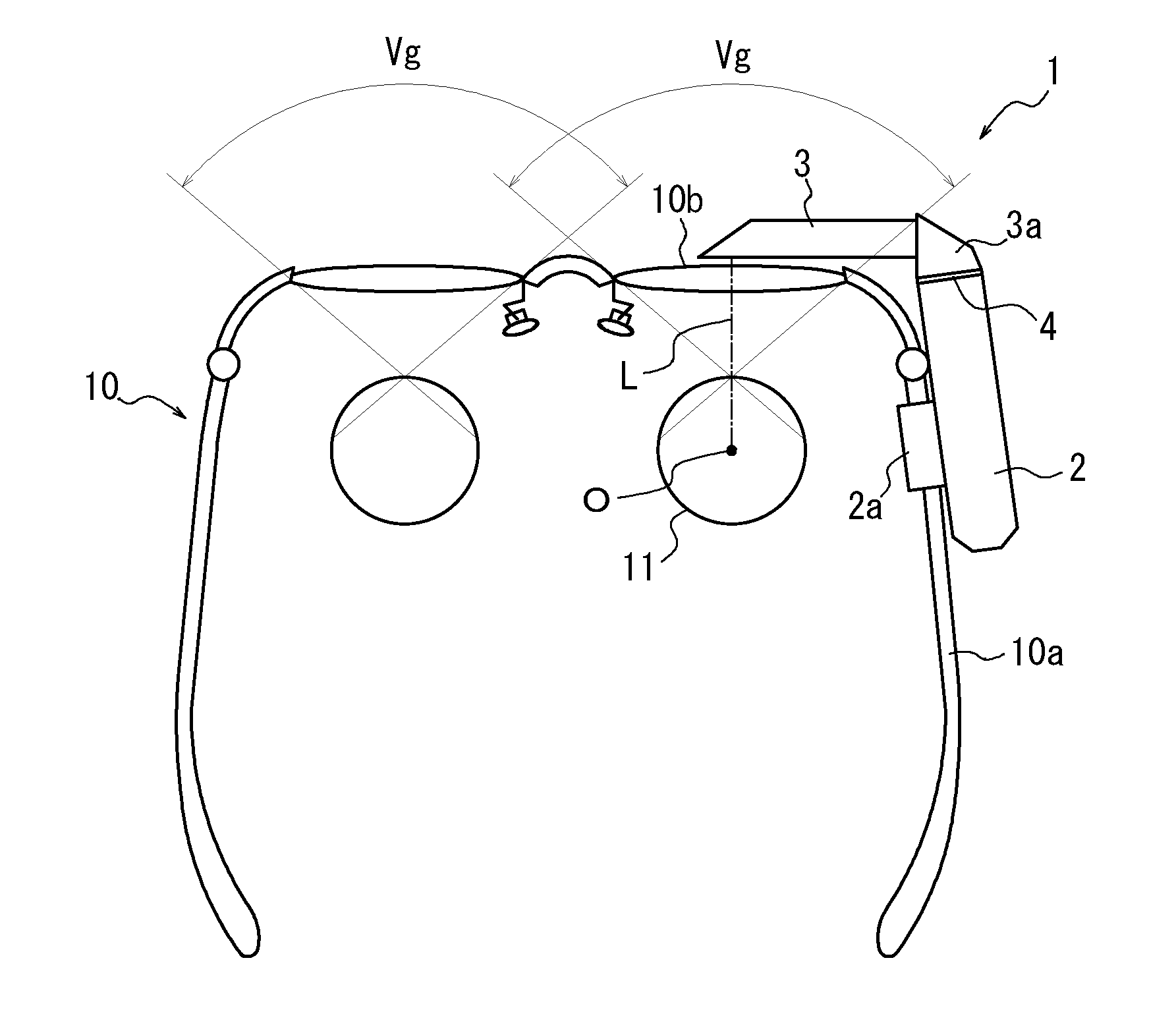
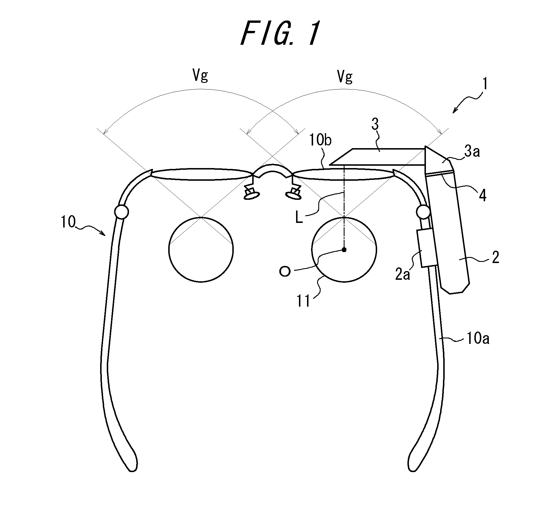
[0117]FIG. 1 illustrates a head-mounted type display device mounted on spectacles according to a first embodiment of the present invention.

[0118]The head-mounted type display device 1 mainly comprises a body unit 2 and an eyepiece optical unit 3. The body unit 2 is fixedly supported on a spectacle frame 10a of spectacles 10 mounted on a user's head at the right temple portion via a spectacle fixture unit 2a. Accordingly, the support portion is adapted to include the spectacle fixture unit 2a.

[0119]The body unit 2 extends along the spectacle frame 10a and forward from the user's point of view. The body unit 2 has a tip that is mounted, lateral to the right spectacle lens, on a mirror frame 3a of the eyepiece optical unit 3 via an attachment portion 4, which will be described below. The eyepiece optical unit 3 extends substantially horizontally from the attachment portion 4 located outside the visual field through the spectacles (Vg) into a user's visual field, in front of the right ...

second embodiment

[0143]FIG. 8 is a diagram for explaining respective optical systems when first and second eyepiece optical units of a head-mounted type display device according to a second embodiment of the present invention are used. FIGS. 8(a) and 8(b) each illustrate, as viewed from above, a portion including the display panel 2b and the first eyepiece optical unit 3-1 or the second eyepiece optical unit 3-2 with the eyepiece optical units 3-1 and 3-2 mounted on the spectacles, along with the shape of each light guide unit 3b1, 3b2 as viewed from the eyeball 11 (as illustrated at the top of the figures).

[0144]As illustrated in FIG. 8(a), the first eyepiece optical unit 3-1 has a light guide unit 3b1, an eyepiece lens 3c1 and an incident window 3d1. Image light incident from the display panel 2b on the incident window 3d1 propagates through the light guide unit 3b1 while being reflected internally, exits the eyepiece lens 3c1, and then is diagonally incident on the front right side of the eyeball...

third embodiment

[0157]FIG. 12 is a diagram for explaining the configuration and operation of a second eyepiece optical unit applicable to a head-mounted type display device according to a third embodiment of the present invention. In this embodiment, it is assumed that the second eyepiece optical unit of the first embodiment is replaced with a second eyepiece optical unit 3-2 of this embodiment as illustrated in FIG. 12. The replaced eyepiece optical unit may also be the first eyepiece optical unit.

[0158]The second eyepiece optical unit 3-2 as illustrated in FIG. 12 comprises a light guide unit 3b2 and an eyepiece lens 3c2. The light guide unit comprises a tip portion having a width of 4 mm or more. The light guide unit 3b2 is shaped as follows: a triangular prismatic portion (a prismatic portion 3g2) is added on the top portion of a rod-shaped light guide unit, wherein the rod-shaped light guide unit, which is arranged in a horizontal direction at the incident side, has a rectangular cross-section...


PUM


Abstract

A head-mounted type display device includes: a spectacle frame for fixture to a user's head; a body unit 2 fixed to the spectacle frame and having an image output unit from which image output unit image light of an image to be displayed is output; an eyepiece optical unit 3 for allowing image light output from the image output unit to be incident on the eyepiece optical unit, for guiding the incident image light to the corresponding eyeball 11 of the user with the spectacle frame being mounted on the user's head, and for displaying, as a virtual image, a magnified version of the image from the image output unit within a user's visual field; and an attachment means 4 for attaching the eyepiece optical unit 3 to the body unit in a replaceable manner. The attachment means 4 may attach at least first and second eyepiece optical units to each other in a replaceable manner, the first and second eyepiece optical units having different optical axis paths L in optical systems for guiding the image light from the image output unit to the eyeball 11.

Description

CROSS-REFERENCE TO RELATED APPLICATION[0001]This application claims priority to Japanese Patent Application Nos. 2010-68784, 2010-68787, 2010-68776 and 2010-68782, filed on Mar. 24, 2010, the contents of which are incorporated herein by reference in their entireties.TECHNICAL FIELD[0002]The present invention generally relates to head-mounted type display devices.BACKGROUND OF THE INVENTION[0003]Conventionally, head-mounted type display devices have different optimum optical specifications for different applications, such as for image viewing or mobile applications, and thus require separate devices to be prepared for the applications. For example, for image viewing applications, such specifications are preferable where a large-screen image can be displayed in front of a viewer within his / her visual field; for mobile applications, it is preferable to, for example, display an image at an end within the visual field while ensuring the outside visual field.[0004]However, it is costly to...

Claims


Application Information

Patent Timeline
IPC IPC(8): G09G5/00G02B27/01
CPCG02B6/0018G02B27/0172G02B27/0176G02C9/00G02B2027/0178G02C1/00G02B2027/0156
Inventor SUGIHARA, RYOHEITATSUTA, SEIJIIBA, YOICHI
Owner OLYMPUS CORP
Why Eureka
Try Eureka