Imaging apparatus

a technology of imaging apparatus and lens, which is applied in the field of imaging apparatus, can solve the problems of insufficient lens, insufficient pressing and contact strength of the case, and increased size of the apparatus, and achieves the effect of reducing the degree of freedom, ensuring sealing capability around an optical element, and appropriating optical capability

Inactive Publication Date: 2011-09-29
RICOH KK
View PDF20 Cites 76 Cited by
  • Summary
  • Abstract
  • Description
  • Claims
  • Application Information

AI Technical Summary

Benefits of technology

[0011]An object of the present invention is to provide an imaging apparatus capable of obtaining an appropriate optical capability without interrupting downsizing while

Problems solved by technology

Here, since downsizing in an imaging apparatus is desired, in the positioned and fixed unit, it is undesirable that the engagement part be at a position protruding relative to a substrate, on which the image pickup device is provided, when viewed in an orthogonal direction to the photographing optical axis, because the imaging apparatus grows in size.
As a result, the downsizing in the imaging appar

Method used


Image

  • Imaging apparatus
  • Imaging apparatus
  • Imaging apparatus

Examples


first embodiment

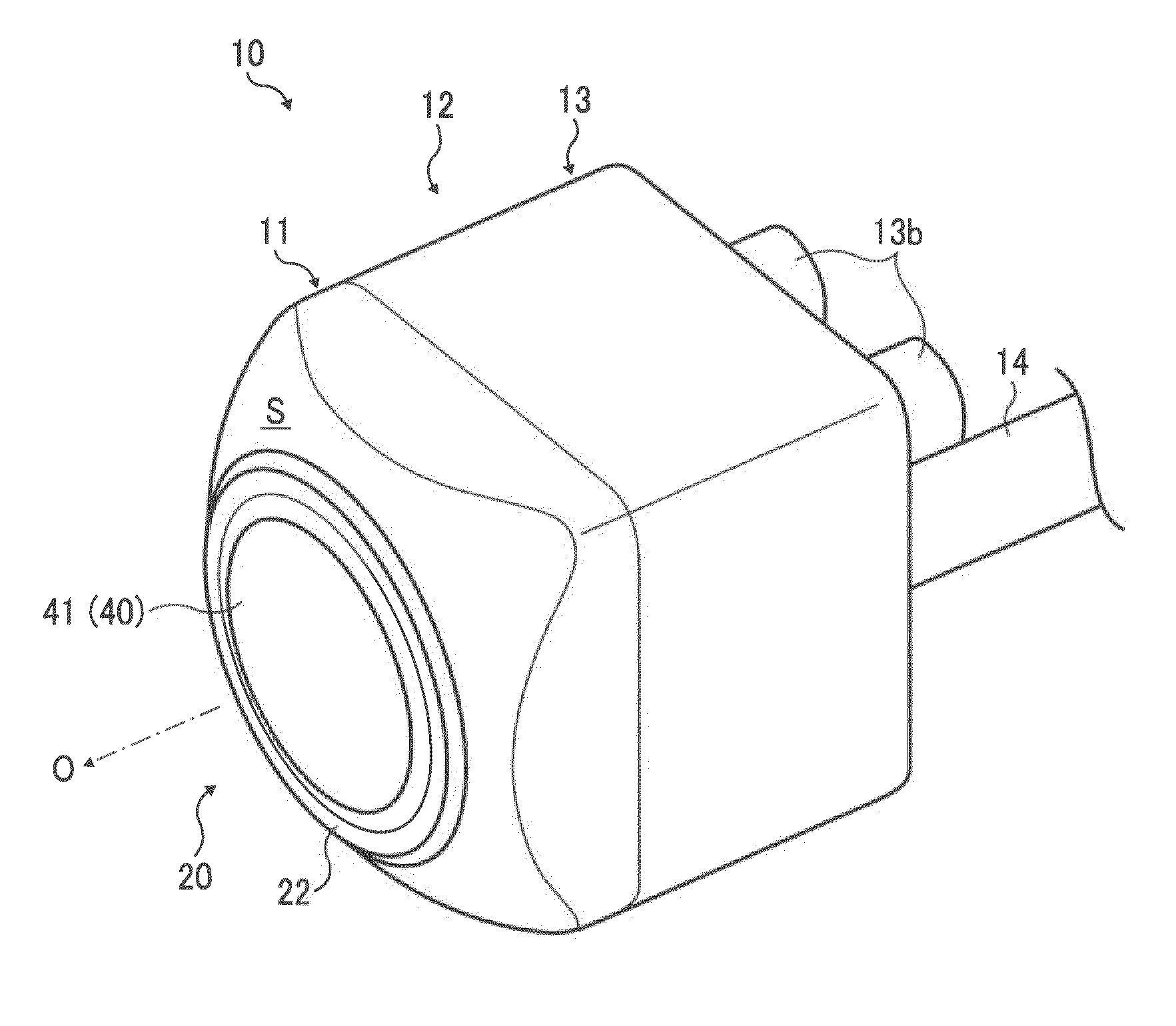
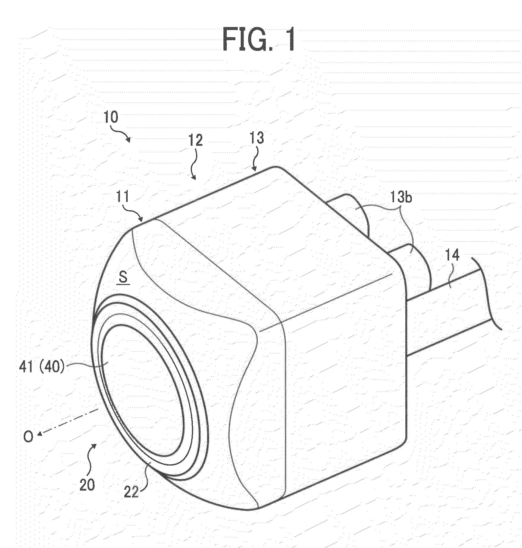
[0038]An imaging apparatus 10 of a first embodiment as an example of an imaging apparatus according to the present invention will be explained with reference to FIGS. 1 to 18.

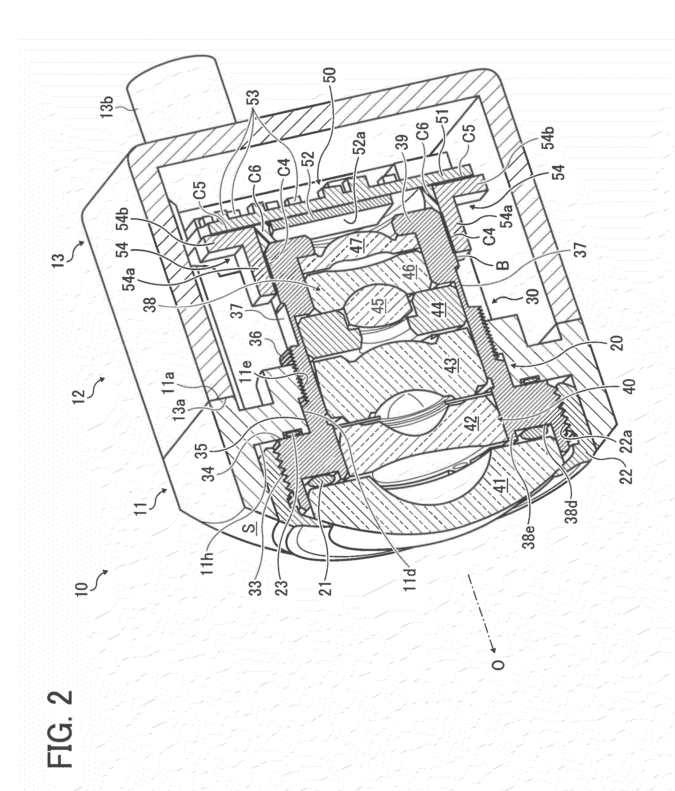
[0039]An imaging apparatus 10 according to an embodiment of the present invention includes, for example, as shown in FIG. 2, at least one optical element, for example, a lens 41 configured to form an image of an object, a lens barrel 30 retaining the at least one optical element, an image pickup device section having an image pickup device 52 and configured to obtain the image of the object formed by the at least one optical element, a mounting wall portion 11 surrounding one end portion of the lens barrel 30 at an object side, a lens-barrel side screw groove, that is, a screw groove 36 provided on an outer circumference surface of the lens barrel 30, and a screw fixation section, that is, a positioning surface 11d and a screw groove 11e provided on the mounting wall portion 11 and configured to screw with the ...

second embodiment

[0112]Next, an imaging apparatus 102 according to a second embodiment of the present invention will be explained. The second embodiment is an example in which the bond structure to bond the electric equipment substrate portion 50 (the substrate 51) and the lens barrel 30 is different from that in the first embodiment. Since a fundamental configuration of the imaging apparatus 102 in the second embodiment is similar to that of the imaging apparatus 10 in the first embodiment mentioned above, the same reference code is used for a part of the same configuration, and a detailed explanation thereof will be omitted. FIG. 20 is a schematic perspective view showing the imaging apparatus 102 according to the second embodiment, which is partially broken, as FIG. 16, for explaining the configuration of the imaging apparatus 102.

[0113]The bond structure may include the indirect bond structure having an intermediate retaining member 542 having one end which forms a lens-barrel side bond surface ...

third embodiment

[0128]Next, an imaging apparatus 103 according to a third embodiment of the present invention will be explained. The third embodiment is an example in which the bond structure to bond an electric equipment substrate portion 503 (the substrate 51) and the lens barrel 30 is different from the first and second embodiments. Since a fundamental configuration of the imaging apparatus 103 in the third embodiment is similar to that of the imaging apparatus 10 in the first embodiment mentioned above, the same reference code is used for a part of the same configuration, and a detailed explanation thereof will be omitted. FIG. 21 is a schematic perspective view showing the imaging apparatus 103 according to the third embodiment, which is partially broken similarly to FIG. 2, for explaining the configuration of the imaging apparatus 103. FIG. 22 is a schematic perspective view showing the imaging apparatus 103 according to the third embodiment, which is partially broken similarly to FIG. 16, fo...


PUM


Abstract

An imaging apparatus includes an optical element forming an image of an object, a lens barrel retaining the optical element, an image pickup device section having an image pickup device and obtaining the image of the object, a mounting wall portion surrounding one end portion of the lens barrel at an object side, a lens-barrel side screw groove provided on an outer circumference surface of the lens barrel, and a screw fixation section provided on the mounting wall portion and screwing with the lens-barrel side screw groove to fix the lens barrel to the mounting wall portion while pressing the one end portion of the lens barrel to the mounting wall portion in a direction of a photographing optical axis.

Description

CROSS REFERENCE TO RELATED APPLICATIONS[0001]The present application is based on and claims priority from Japanese Application Number 2010-075305, filed on Mar. 29, 2010, the disclosure of which is hereby incorporated by reference herein in its entirety.BACKGROUND OF THE INVENTION[0002]1. Field of the Invention[0003]The present invention relates to an imaging apparatus used as a digital camera, a digital video camera, or the like, more specifically, to an imaging apparatus suitable for an in-vehicle camera.[0004]2. Description of the Related Art[0005]Conventionally, an imaging apparatus including an optical element such as an imaging lens and an image pickup device such as a CCD (Charge Coupled Device) and a CMOS (Complementary Metal Oxide Semiconductor) is generally applied to an in-vehicle camera, a digital camera, a digital video camera, or the like. The imaging apparatus is generally housed in a case in a state where an image to be formed by the optical element (the lens) is pos...

Claims


Application Information

Patent Timeline
IPC IPC(8): H04N5/225H04N7/18
CPCH04N5/2257H04N5/2254H04N23/57H04N23/55
Inventor NAKAJIMA, MITSURUOGATA, TETSUYA
Owner RICOH KK
Why Eureka
Try Eureka