
Display apparatus

Inactive Publication Date: 2011-09-29
FUJIFILM CORP
View PDF8 Cites 156 Cited by
  • Summary
  • Abstract
  • Description
  • Claims
  • Application Information

AI Technical Summary

Benefits of technology

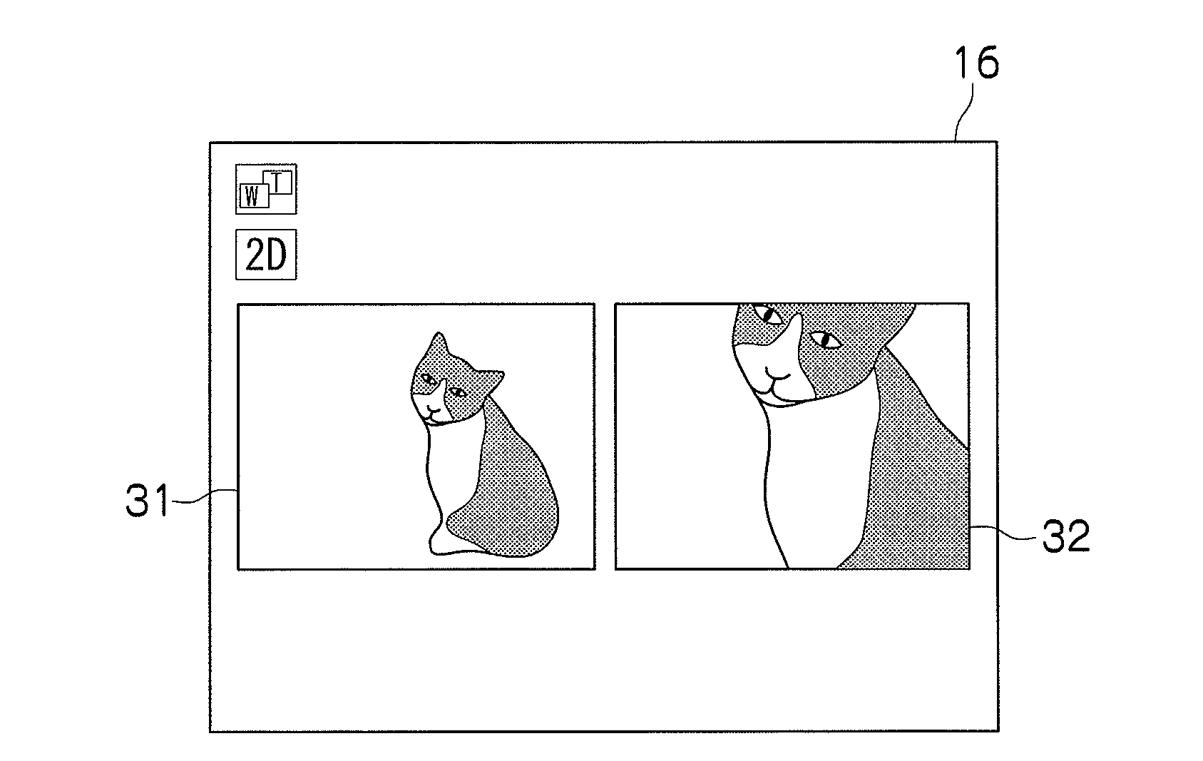
[0011]According to the display apparatus of the first aspect, associated and stored two plane images taken at the same time in different photographing ranges are acquired, and the acquired two plane images are displayed by at least one of the first display method, the second display method, and the third display method. The first display method is a display method for displaying desired one of the two plane images on the entire screen and reducing and displaying the other plane image, the second display method is a display method for displaying the two plane images side by side, and the third display method is a display method for displaying desired one of the two plane images over the other plane image at a predetermined transmittance and changing the predetermined transmittance along with the passage of time. As a result, the images can be watched with high visibility while maintaining the relationship between two images.
[0019]In the display apparatus of the fifth aspect, the other of the two plane images is displayed over the desired one plane image at 100% transmittance, the transmittance is gradually reduced from 100% along with the passage of time, and the desired one plane image can be designated. This allows the user to arbitrarily select whether to enlarge or reduce the images.
[0023]In the display apparatus of the seventh aspect, one file consecutively storing the two plane images is acquired to acquire the associated and stored two plane images taken at the same time in different photographing ranges. As a result, the two plane images are not scattered, and the relationship between the two plane images can be easily understood during reproduction.

Problems solved by technology

However, the image actually displayed on the display unit is an image before enlargement (zooming), and there is a problem that the user cannot check the details of the image.
Therefore, as in the invention described in Japanese Patent Application Laid-Open No. 2006-238326, there is a problem that the user cannot check the details of the images.
There is also a problem that two display units are required to display two images in the second mode of the invention described in Japanese Patent Application Laid-Open No. 2004-207774.

Method used


Image

  • Display apparatus
  • Display apparatus
  • Display apparatus

Examples


first embodiment

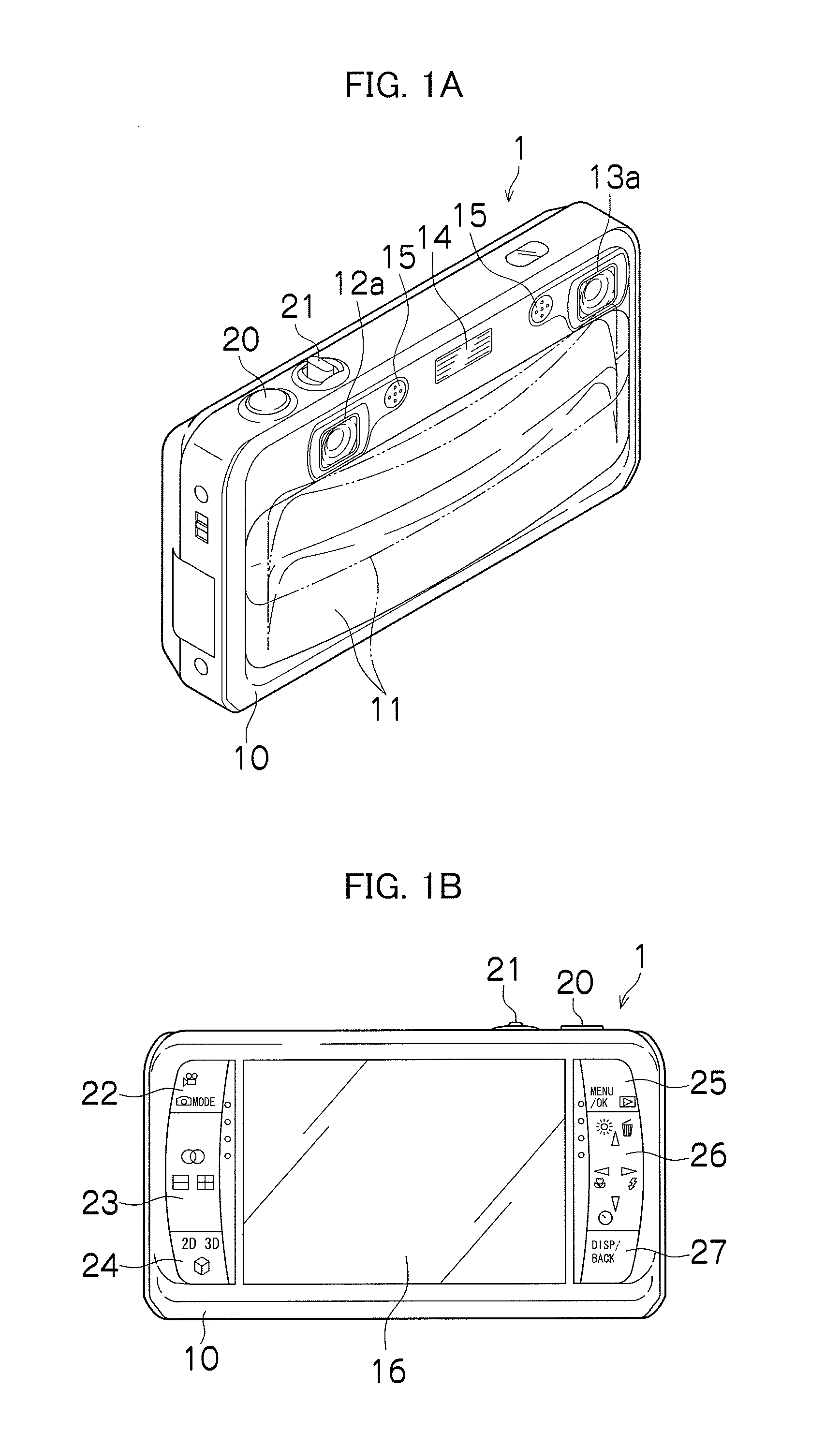
[0046]FIGS. 1A and 1B are schematic diagrams of a compound-eye digital camera 1 as the compound-eye imaging apparatus according to the presently disclosed subject matter. FIG. 1A is a front view, and FIG. 1B is a back view. The compound-eye digital camera 1 includes a plurality of (two are illustrated in FIGS. 1A and 1B) imaging systems, and the compound-eye digital camera 1 is capable of taking a stereoscopic image depicting a single subject from a plurality of viewpoints (left and right two viewpoints are illustrated in FIGS. 1A and 1B) as well as a single-viewpoint image (two-dimensional image). The compound-eye digital camera 1 can record and reproduce not only still images but also moving images and sound.

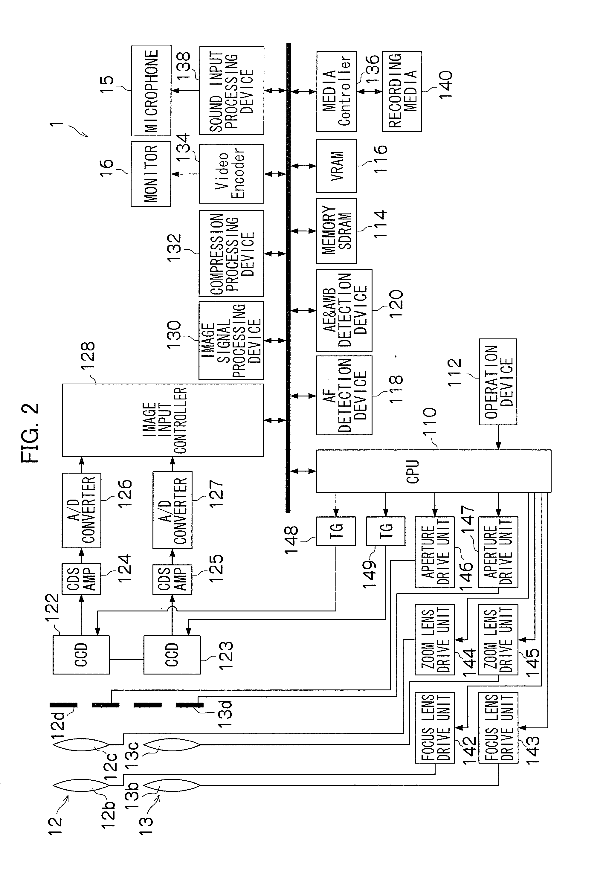
[0047]A camera body 10 of the compound-eye digital camera 1 is formed in a substantially rectangular-solid-box shape. As shown in FIG. 1A, a barrier 11, a right imaging system 12, a left imaging system 13, a flash 14, and a microphone 15 are mainly arranged on the front side o...

second embodiment

[0190]In the first embodiment of the presently disclosed subject matter, the display method displayed on the monitor 16 just before shooting of the still images or the moving images is stored in the ancillary information of the file in which the images taken in the tele / wide simultaneous shooting mode are associated and stored. However, the display method for storing the ancillary information is not limited to this.

[0191]A second embodiment of the presently disclosed subject matter is a mode for allowing input of a display method when moving images are taken in the tele / wide simultaneous shooting mode and storing the inputted display method in real time. In a compound-eye digital camera 3 of the second embodiment, only a moving image shooting process in the tele / wide simultaneous shooting mode is different from the compound-eye digital camera 1 of the first embodiment. Therefore, only the moving image shooting process in the tele / wide simultaneous shooting mode will be described, an...


PUM


Abstract

Provided is a display apparatus that allows viewing a plurality of plane images in different photographing ranges with high visibility. Two images in different photographing ranges (an image of the telephoto side and an image of the wide side) are taken in a tele / wide simultaneous shooting mode, and the two images are stored in one image file (for example, MP file). The display apparatus acquires the image file and displays the two images on a monitor by a display method stored in ancillary information of the image file. A change in the display method can be inputted from an designation device. If the display method is inputted, a CPU causes the monitor to display the images by the changed display method. If the display method is inputted, the ancillary information of the image file is overwritten by the inputted display method and stored in a main memory.

Description

BACKGROUND OF THE INVENTION[0001]1. Field of the Invention[0002]The presently disclosed subject matter relates to a display apparatus, and particularly, to a display apparatus that displays a plurality of plane images in different photographing ranges after the plane images are taken.[0003]2. Description of the Related Art[0004]Japanese Patent Application Laid-Open No. 2006-238326 proposes a video camera in which an image taken by 3× optical zooming is displayed on a display unit when an instruction of more than 3× zooming is inputted in a camera capable of 3× optical zooming, and a range to be enlarged is surrounded by a frame by electronic zooming.[0005]Japanese Patent Application Laid-Open No. 2004-207774 proposes a digital camera in which subject images are formed in two imaging elements in different sizes, an image taken by a larger imaging element (wide imaging element) is displayed on a display unit, and a range to be imaged by a smaller imaging element (telephoto imaging ele...

Claims


Application Information

Patent Timeline
IPC IPC(8): H04N5/225H04N13/239
CPCH04N5/2251H04N13/0239H04N5/23296H04N5/23245H04N13/239H04N23/50H04N23/667H04N23/631H04N23/635H04N23/69
Inventor WAKABAYASHI, SATORUHAYASHI, JUNJI
Owner FUJIFILM CORP
Learn More