Moving head fixture and cooling module

a technology of moving head and cooling module, which is applied in the direction of lighting heating/cooling arrangements, air heaters, lighting applications, etc., can solve the problems of large light device size, cooling system above-described cannot be applied in the light fixture with moving head, and further limited space in the moving head

Active Publication Date: 2011-09-29
MARTIN PROFESSIONAL
View PDF10 Cites 36 Cited by
  • Summary
  • Abstract
  • Description
  • Claims
  • Application Information

AI Technical Summary

Benefits of technology

[0007]Hereby it is possible to create a compact moving head light fixture where both the LEDs and electronic drive circuits are effectively cooled. This is achieved by positioning the LEDs on the first cooling plate and the electronic circuit for LED control on the second cooling plate. The air flow passage makes it possible to lead air between the cooling plates, as the air passage runs through at least one of the cooling plates and forms a tunnel between the first and second cooling plates, which is helpful for the air flow and whereby both the LEDs and electric circuits are cooled using the same air. The size of the light fixture could be more compressed, as both the LEDs and the electric circuits could be cooled using the same air. Moreover, the LEDs are placed on the first cooling plate and the electronic circuit for LED driving is arranged on the second cooling plate, thus the configuration is capable of directly conducting the heat produced by the LEDs and the driver respectively to an outer shell of the moving head. Further it is possible to cool the LEDs and electronic circuits for LED control from the inside and out, as the air passage runs through one on the cooling plates. This is advantageously, as the LEDs and the electronic circuits for LED control positioned at the centre of the cooling plates tend to be the hottest and by cooling from the inside and out makes sure that the hottest parts are cooled first. The position where the air passage goes through the cooling plates can thus be positioned at the near the hottest places.
[0017]Hereby a compact cooling module for a moving head could be constructed and the same technical effects and advantages as described above are achieved. Further by the cooling module improves the serviceability of the moving head as it could be constructed as one module which easily could be remove from and replaced in the moving head. For instance in connection with service and / or cleaning.

Problems solved by technology

However, for the three light sources are arranged on the same plane, the disadvantage of the above illuminating device and projection type video display is the size of the light device is large and the light sources of the device are not movable, thus, the cooling system above-described could not applied in the light fixture with moving head.
The space in a moving head is further very limited compared to the Illuminating device and projection type video display of US2005219841, and the electronic circuits for LED control thus are positioned very close to the LEDs, and a further demand on cooling is needed, since the LED control circuits also generate heat.
It is in many applications such as in connection with projectors and moving heads impossible to position the driver board in a drive box which is separated from the LED housing.

Method used


Image

  • Moving head fixture and cooling module
  • Moving head fixture and cooling module
  • Moving head fixture and cooling module

Examples


Embodiment Construction

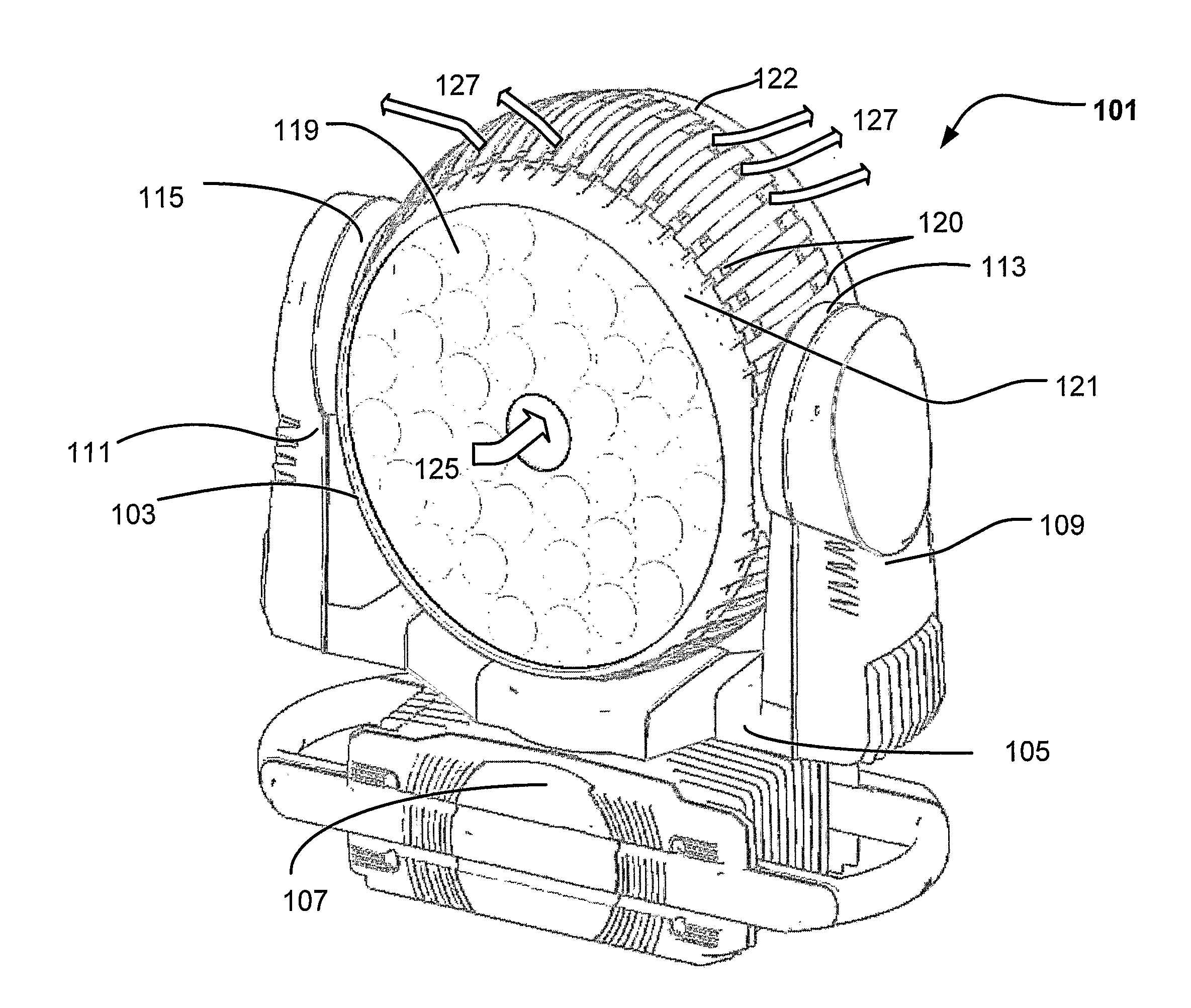
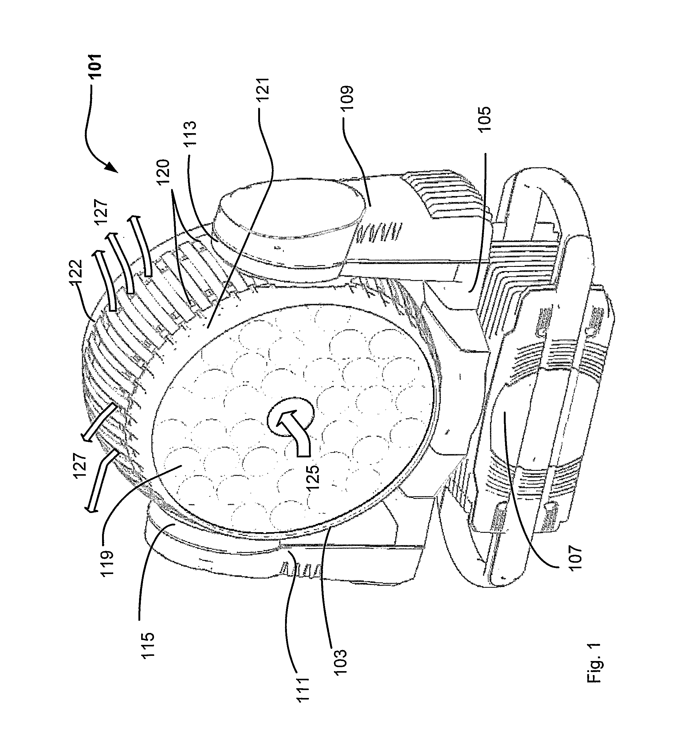
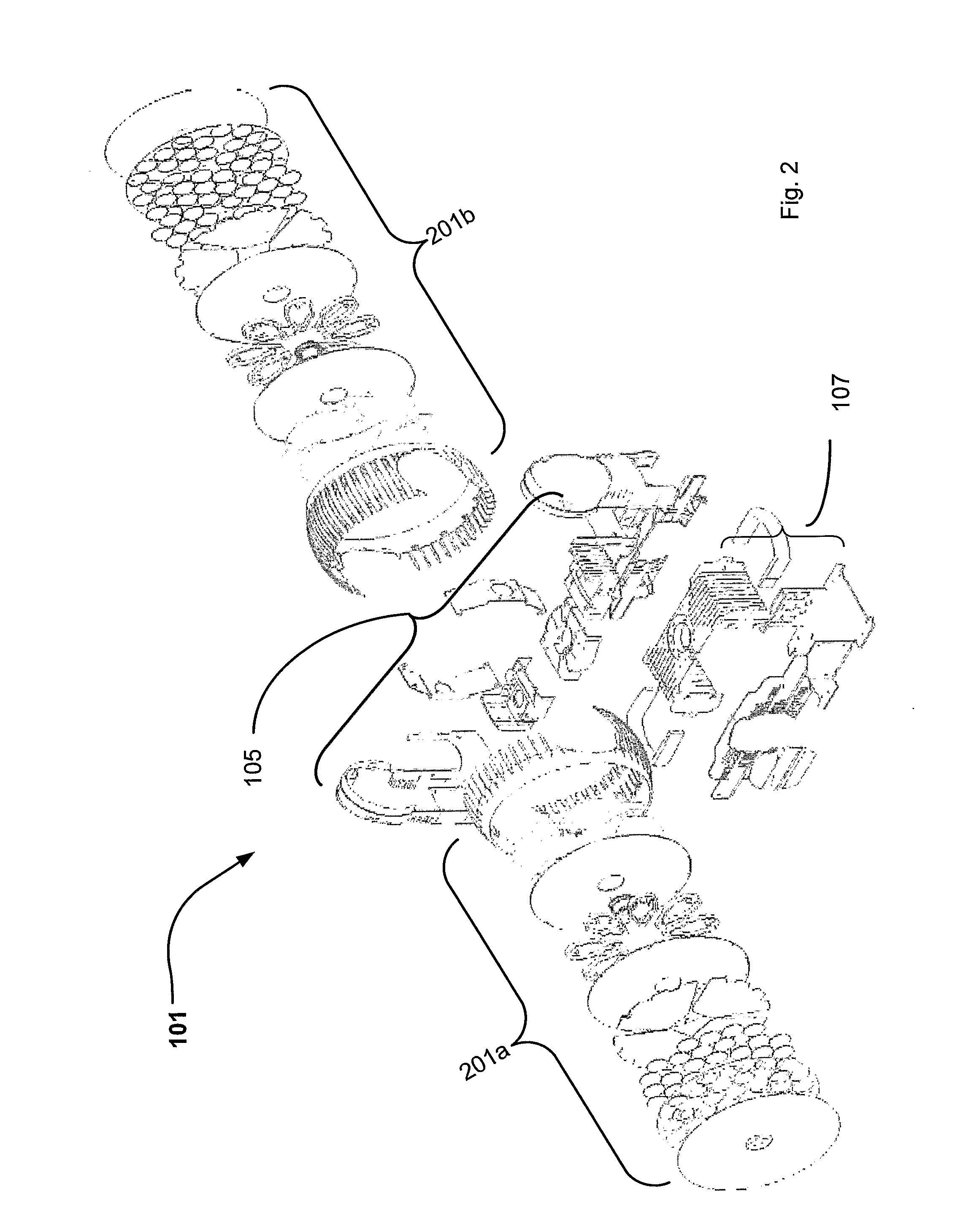
[0006]The object of the present invention is to solve the above described problems. This can be achieved by a moving head light fixture, which moving head light fixture comprises a light generating head, which head is carried in a yoke, which head is rotatable to the yoke, which yoke is rotatable to a base, which head comprises at least one electronic circuit for LED control, further said moving head comprises a first cooling plate comprising a number of LEDs; a second cooling plate comprising said at least one electronic circuit for LED control; and an air flow passage running from one at least one end of said moving head, through at least said first cooling plate or said second cooling plate and between said first cooling plate and said second cooling plate.

[0007]Hereby it is possible to create a compact moving head light fixture where both the LEDs and electronic drive circuits are effectively cooled. This is achieved by positioning the LEDs on the first cooling plate and the ele...


PUM


Abstract

The present invention relates to a moving head light fixture, which moving head light fixture comprises a light generating head, which head is carried in a yoke, which head is rotatable to the yoke, which yoke is rotatable to a base, which head comprises at least one electronic circuit for LED control, where the moving head comprises a first cooling plate comprising a number of LEDs; a second cooling plate comprising said at least one electronic circuit for LED control; and an air flow passage running from at least one end of said moving head, through at least said first cooling plate and / or said second cooling plate and between said first cooling plate and said second cooling plate. The present invention relates also to a cooling module for a moving head.

Description

FIELD OF THE INVENTION[0001]The present invention relates to a moving head light fixture, which moving head light fixture comprises a light generating head, which head is carried in a yoke, which head is rotatable to the yoke, which yoke is rotatable to a base, which head comprises electronic circuits for LED control.[0002]The present invention further relates to a cooling module for a moving head light fixture.BACKGROUND OF THE INVENTION[0003]Light fixtures currently tend to use light sources with a high lumen, and the light sources are thus provided with high power. The light sources are getting more and more efficient and uses more and more of the supplied energy to generate light; however a considerable part of the power is still generated into heat. For example, arrayed LEDs (light-emitting diode) in a light fixture may have such high power as 500 watts. In this case, it is desired to have a light device with a heat-dissipating system, which works fast and efficiently.[0004]The...

Claims


Application Information

Patent Timeline
Patent Type & Authority Applications(United States)
IPC IPC(8): F21S4/00F28F13/12F21V29/02
CPCF21V21/30F21V29/02F21V29/77F21Y2101/02F21V29/677F21W2131/406F21Y2115/10F21V3/02F21V29/83
Inventor PEDERSEN, ALLANABOLFAZLIAN, MAZYAR
Owner MARTIN PROFESSIONAL
Why Eureka
Try Eureka