Variable directional microphone

a directional microphone and variable technology, applied in the direction of transducer details, electrical transducers, electrical apparatus, etc., can solve the problems of affecting the low frequency limit, turbulence is easily produced, and the dynamic microphone unit has scarcely been used, so as to improve the directional frequency response and shorten the distance between the acoustic terminals. the effect of distan

Inactive Publication Date: 2011-09-29
AUDIO-TECHNICA
View PDF2 Cites 19 Cited by
  • Summary
  • Abstract
  • Description
  • Claims
  • Application Information

AI Technical Summary

Benefits of technology

By arranging the rear air chamber on the outside between the dynamic microphone units via the predetermined tube member, the distance between acoustic terminals (distance between diaphragms of the units) is shortened, so that better directional frequency response can be obtained.

Problems solved by technology

Therefore, as the microphone unit, a small-size unidirectional condenser microphone has been used frequently, and a dynamic microphone unit has scarcely been used because of its large size.
However, in the case where the capacity Ca of the rear air chamber 1b is low, the low frequency limit is affected.
Therefore, there arises a problem that the difference (phase difference) between arrival times of sound waves to the acoustic terminals from the sound source increases, so that turbulence is easily produced especially in a high sound range.
Therefore, there arises a problem of deteriorated directional frequency response.

Method used


Image

  • Variable directional microphone
  • Variable directional microphone
  • Variable directional microphone

Examples


first embodiment

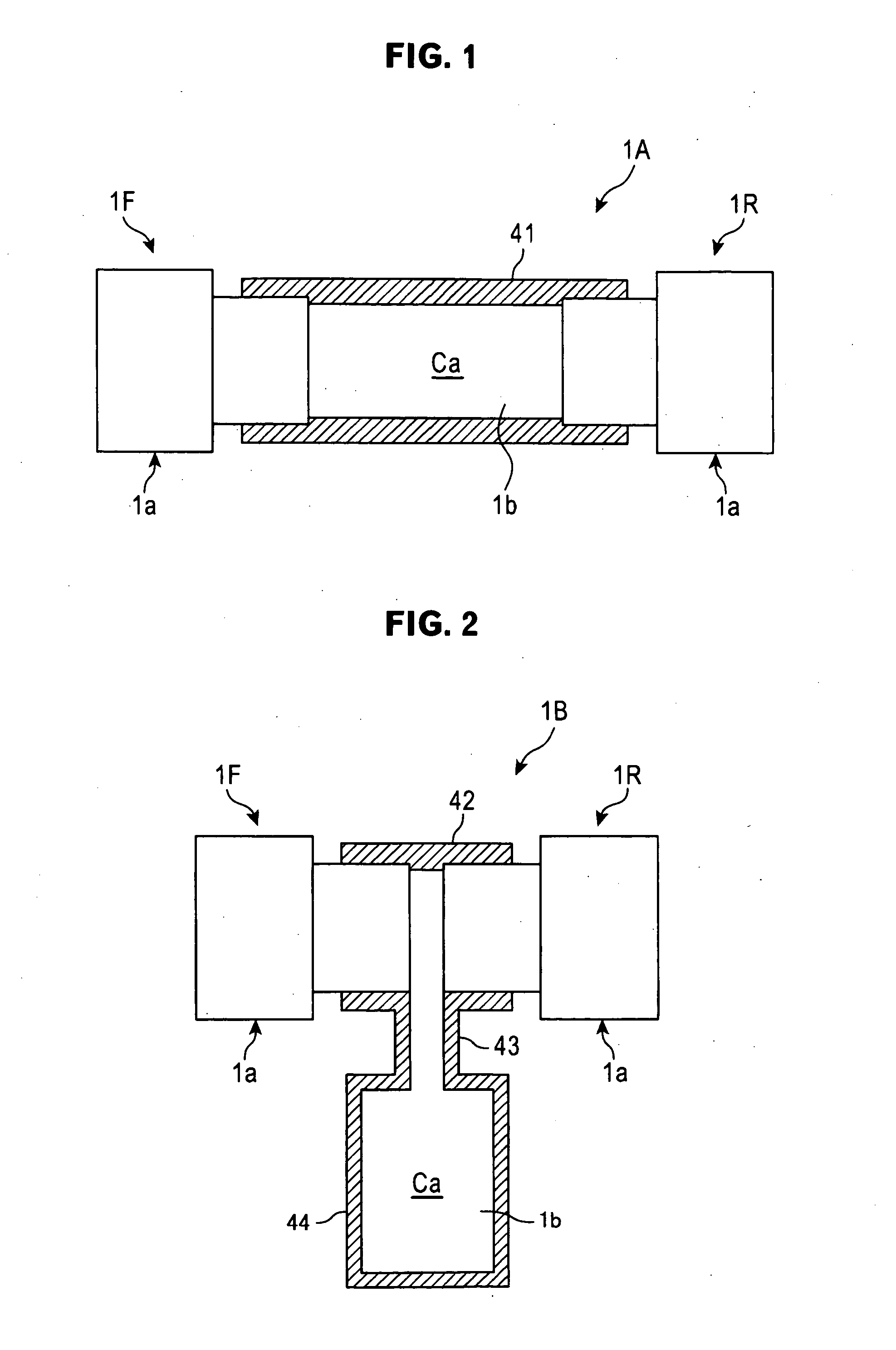
First, a variable directional microphone 1A in accordance with the present invention is explained with reference to FIG. 1. This variable directional microphone 1A includes two unidirectional dynamic microphone units 1F and 1R.

In this embodiment, one dynamic microphone unit 1F is a front-side unit that is directed to the sound source side when sound is picked up. In contrast, the other dynamic microphone unit 1R is a rear-side unit that is directed to the rear with respect to the sound source. In the following explanation, one dynamic microphone unit IF is sometimes referred simply to as a “front-side unit 1F”, and the other dynamic microphone unit 1R is sometimes referred simply to as a “rear-side unit 1R”.

The front-side unit 1F and the rear-side unit 1R have substantially the same configuration, and each are provided with an electrokinetic acousto-electric converter 1a that is similar to that explained before with reference to FIG. 10A.

That is, referring to FIG. 10A, the electroki...

second embodiment

Next, a variable directional microphone 1B in accordance with a second embodiment is explained with reference to FIG. 2. In this variable directional microphone 1B, to further shorten the distance between the acoustic terminals of the front-side unit 1F and the rear-side unit 1R, the rear air chamber 1b used in common by the front-side unit 1F and the rear-side unit 1R is disposed on the outside between the units.

In this second embodiment, therefore, as a connecting cylinder for coaxially connecting the electrokinetic acousto-electric converters 1a of the front-side unit 1F and the rear-side unit 1R to each other, a connecting cylinder 42 that is shorter than the connecting cylinder 41 in the first embodiment is used.

The connecting cylinder 42 is integrally formed with an air chamber housing 44 connected to the connecting cylinder 42 between the electrokinetic acousto-electric converters 1a via a tube part 43. In this case, the sum of the capacity in the air chamber housing 44, the ...


PUM


Abstract

There is provided a variable directional microphone including dynamic microphone units that is small in size and has good directional frequency response. In a variable directional microphone 1A in which a unidirectional first dynamic microphone unit (front-side unit) 1F and a second dynamic microphone unit (rear-side unit) 1R, which has substantially the same configuration as that of the front-side unit 1F and is provided with an output adjusting means of sound signal, are provided as a pair; the front-side unit 1F and the rear-side unit 1R are arranged coaxially so that the directivity axes thereof are directed to the directions 180° opposite to each other; and the output signals of the front-side unit 1F and the rear-side unit 1R are generated via a signal synthesis circuit, one rear air chamber 1b is used in common by the front-side unit 1F and the rear-side unit 1R.

Description

CROSS-REFERENCE TO RELATED APPLICATIONThe present application is based on, and claims priority from, Japanese Application Serial Number JP2010-066093, filed Mar. 23, 2010, the disclosure of which is hereby incorporated by reference herein in its entirety.TECHNICAL FIELDThe present invention relates to a variable directional microphone. More particularly, it relates to a variable directional microphone configured by two unidirectional dynamic microphone units.BACKGROUND ARTBy synthesizing sound signals generated from two microphone units by using a variable directional microphone configured by the two microphone units, directivity such as omnidirectivity, cardioid, hypercardioid, or bidirectivity can be obtained selectively.In this case, as both of the two microphone units, unidirectional microphone units are used, and the microphone units are arranged coaxially so that the directivity axes thereof are directed to the directions opposite to each other (180° directions) (for example, ...

Claims


Application Information

Patent Timeline
Patent Type & Authority Applications(United States)
IPC IPC(8): H04R3/00
CPCH04R1/245H04R1/2807H04R9/08H04R3/005H04R1/406
Inventor OKITA, SHIOTO
Owner AUDIO-TECHNICA
Why Eureka
Try Eureka