Liquid heater with temperature control

a technology of liquid heater and temperature control, which is applied in the direction of liquid transferring device, lighting and heating apparatus, immersion heating arrangement, etc. it can solve the problems of “thermal lag or delay” and the power of the semiconductor element itself, so as to prevent the attachment of bubbles and improve the sensing

Active Publication Date: 2011-09-29
OHMIQ INC
View PDF24 Cites 12 Cited by
  • Summary
  • Abstract
  • Description
  • Claims
  • Application Information

AI Technical Summary

Benefits of technology

[0008]A further aspect of the invention provides a fluid handling device which can be used, for example, in a heater as discussed above. The heater according to this aspect of the invention desirably includes a channel structure defining at least one channel extending in a downstream direction and an elongated wire extending across the channel in a widthwise direction adjacent a downstream end of the channel. The device further includes an exit structure bounding the channel at a downstream end of the channel. The exit structure most preferably defines a slot extending across the channel in the widthwise direction in alignment with the wire. The slot desirably has a cross-sectional area smaller than the cross-sectional area of the channel and desirably is open for flow of fluid exiting from the channel. The exit structure prefer...

Problems solved by technology

Thus, the semiconductor elements themselves dissipate very little power, even though substantial electrical currents flow through them when they are in their closed states.
As set forth in the '527 Publication, however, such an arrangement suffers fro...

Method used


Image

  • Liquid heater with temperature control
  • Liquid heater with temperature control
  • Liquid heater with temperature control

Examples


Embodiment Construction

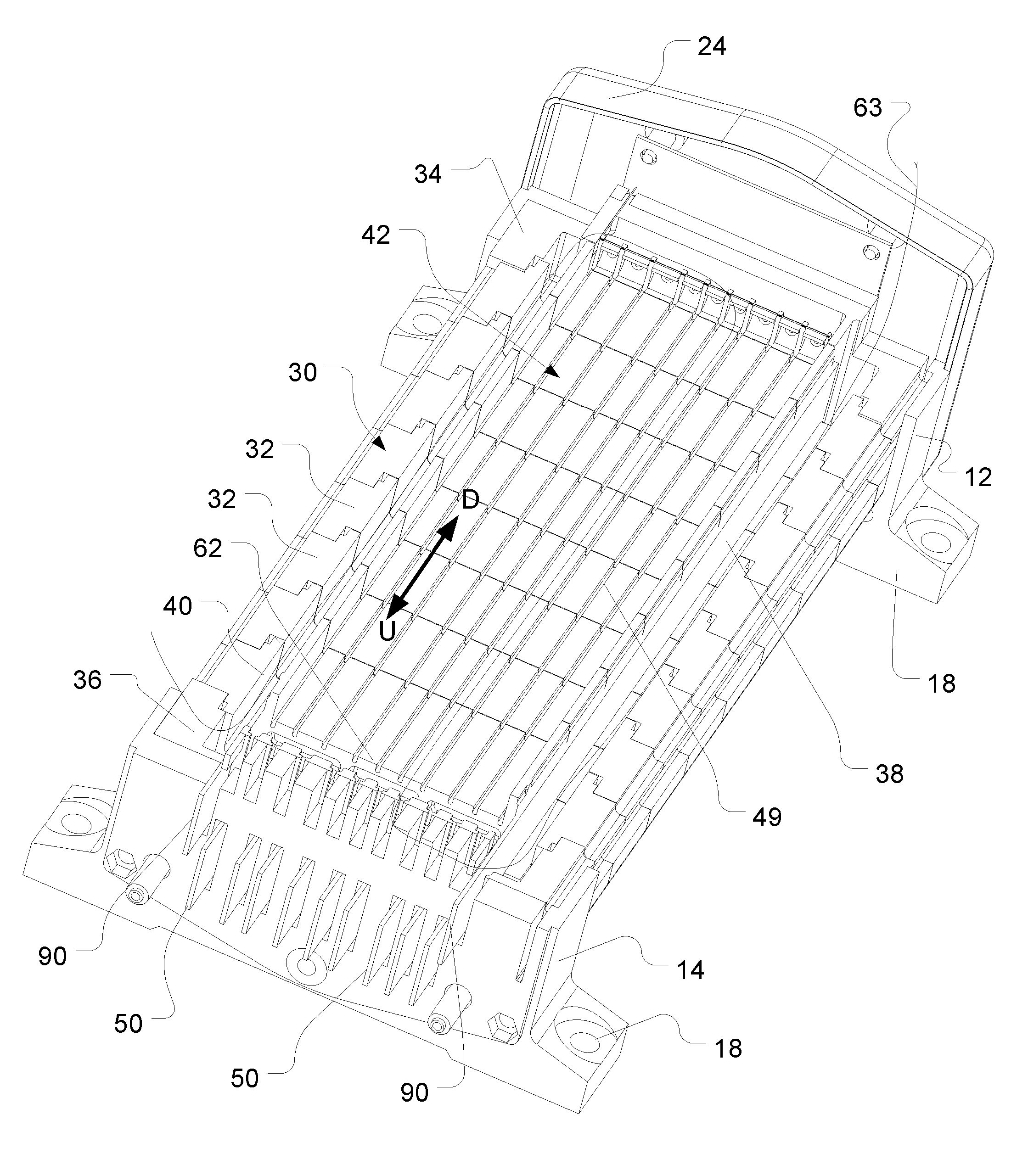
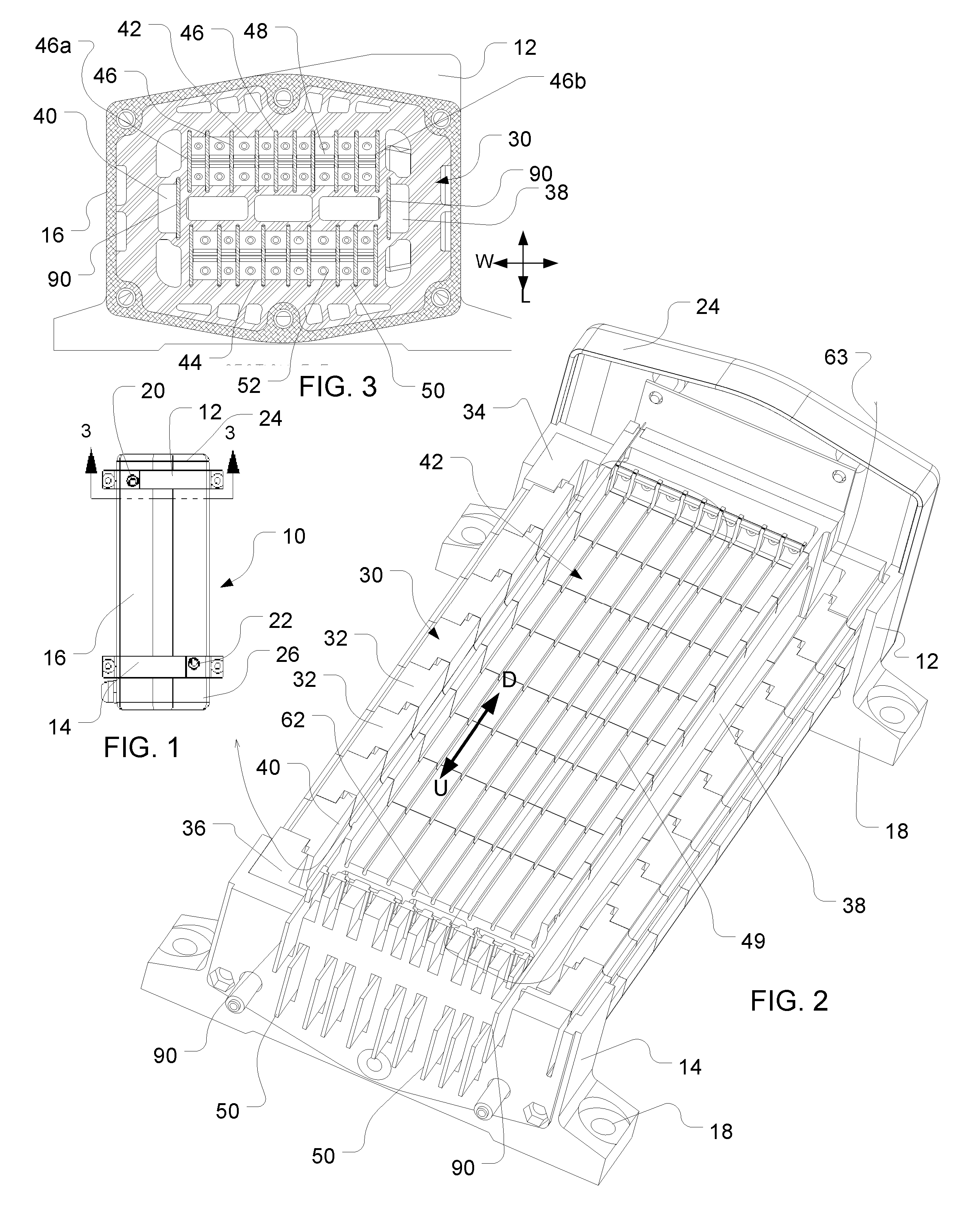
[0016]A heater according to one embodiment of the invention includes a housing 10 (FIG. 1). The housing 10 includes a first end cap 12, second end cap 14, and a generally tubular enclosure 16 extending between these end caps. The first and second end caps are provided with mounting feet 18. The first and second end caps desirably are formed from a metallic material as, for example, a die cast or machined metal. Enclosure 16 desirably has substantially constant cross-section along its length between the end caps and desirably is formed from a metallic material. For example, enclosure 16 may be formed from an extruded metal such as extruded aluminum. Enclosure 16 is removed in FIG. 2 for clarity. Enclosure 16 and caps 12 and 14 cooperatively define a pressure-tight vessel. The first end cap 12 is provided with a fluid inlet port 20, whereas the second end cap 14 has a fluid outlet port 22. A shroud 24 covers the first end cap 20, whereas a further shroud 26 covers the second end cap 1...


PUM


Abstract

A liquid heater such as a direct electrical resistance liquid heater having multiple flow channels is provided with a temperature-sensing element in the form of a wire extending across numerous channels, preferably all of the channels, near the downstream ends of the channels. The resistance of the wire represents the average temperature of the liquid passing through all of the channels, and hence the temperature of the mixed liquid exiting from the heater. A bubble suppressing structure is provided in the vicinity of the wire.

Description

CROSS-REFERENCE TO RELATED APPLICATIONS[0001]The present application is a continuation-in-part of U.S. patent application Ser. No. 11 / 352,184, filed on Feb. 10, 2006 and published as US Patent Application Publication No. US 2006 / 0291527 A1, which application claims benefit of the filing date of U.S. Provisional Patent Application Nos. 60 / 677,552, filed on May 4, 2005; 60 / 709,528, filed on Aug. 19, 2005; and 60 / 726,473, filed on Oct. 13, 2005. The disclosures of all of the aforementioned applications and publication are incorporated herein by reference.FIELD OF THE INVENTION[0002]The present invention relates to liquid heaters, and components thereof.BACKGROUND OF THE INVENTION[0003]As set forth in the aforementioned US Patent Application Publication No. US 2006 / 0291527 A1 (“'527 Publication”), it is advantageous to heat fluids, particularly liquids such as water for use as domestic hot water using a “tankless” heating device. A tankless heating device is intended to heat the fluid a...

Claims


Application Information

Patent Timeline
IPC IPC(8): F24H1/18F24H1/10
CPCF24H1/106F24H9/18F24H9/2028F24H9/1809F24H15/37F24H15/407F24H15/20F24H15/219F24H15/174
Inventor BOWERS, JOHN H.LYON, GREGORY S.
Owner OHMIQ INC
Why Eureka
Try Eureka